Soft-Switching Helps EV Inverters Run Farther, Faster, and Cooler
Members can download this article in PDF format.
What you'll learn:
- Benefits of soft-switching for WBG inverters.
- Types of soft-switching techniques.
- How MCU advances have pushed soft-switching back into automotive and industrial design.
Wide-bandgap (WBG) semiconductors such as gallium nitride (GaN) and silicon carbide (SiC) are essential to the development of high-efficiency traction inverters that can help EV s become increasingly competitive with their internal-combustion-engine (ICE) counterparts. However, their fast switching characteristics and other unique properties also raise several design challenges that must be overcome before their full benefits can be realized.
This article explores a number of techniques, generally classified as “soft switching,” that can be used to help WBG-based inverters achieve their full potential (Fig. 1).
The Promise and Peril of WBG
In theory, WBG devices' low conduction losses help add at least 5% to 10% to the vehicle's range, while dramatically reducing the inverter's size and cooling requirements. In addition, their higher operating frequencies could greatly reduce the amount of EMI they generate, as well as filtering components required to suppress them.
However, to achieve their potential efficiency, care must be taken to minimize the losses (and damaging stray currents) that occur when they’re not switched at the motor's zero-crossing point. In addition, it’s important to minimize the unwanted artifacts generated by high frequencies and sharp rise times that could damage the drive system.1
To overcome these problems, researchers have developed a number of techniques for shaping the inverter's drive signal to ensure that each leg switches between the positive and negative phases of the drive cycle at the zero-crossing point.
Such “soft-switching” techniques enable the inverter to operate efficiently at much higher frequencies, thereby reducing the size of the inverter's dc-link capacitors and associated inductive components. In addition, soft-switching can be used to reduce the slope of the drive waveform's rising and falling edges (dv/dt), which greatly attenuates the electromagnetic interference (EMI) produced by the inverter.
Soft-Switching Basics
A wide variety of approaches are applied for soft-switching. However, they’re all based on the principle of zero-crossing switching to reduce or eliminate switching losses. It eliminates the current and voltage transition overlap that can occur during each switching cycle of the inverter bridge.
When a MOSFET (silicon or WBG) is soft-switched, it reduces or eliminates any voltage or current overlap, which, in turn, can cut switching losses by 90% or more. In a zero-voltage switching regime (ZVS), the soft-switching controller will wait until the bridge's drive voltage drops to zero (not merely its idle state) before the MOSFET is turned on or off. A similar technique, zero-current switching (ZCS), can be employed to switch the MOSFET when the bridge leg's current approaches zero.
ZVS/ZCS switching isn’t a new technology, with various types of analog-based controllers developed at least as early as the early 1990s.2 One of the most common analog-based control architectures is the auxiliary resonant commutated pole (ARCP) inverter, which uses a forced resonant soft-switching circuit topology to adjust the switching control pulse to remain in sync with the zero crossing.
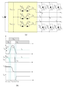
Figure 2a highlights (in yellow) the ARCP circuits used for each of the three phase legs in power-converter designs. The circuit in the first (top) leg of the inverter consists of resonant devices CX1 and CX2 (the sum of which is Cr), Lx1 and active switches Sx1, Sx2, and a pair of rectifiers that sit across the switching transistors.
When the circuit's values are correctly chosen, it creates a forced resonant condition that controls the switch's commutation from low to high where current flows from ground to output, requiring ARCP current injection to force the transition. During commutation from high to low, where current flows from Vbus to the output, the bridge requires only a correct dead time as it is self-commutating.
The circuit also controls the slope of the voltage waveform to limit unwanted dv/dt effects. When SX1 is turned off, the load current is shared between the snubber capacitors (Cs) across S1 and S2, which reduces the dV/dt (dU/dt) across the device. The slower transition time permits S1 to turn off completely before the voltage it sees across its terminals has risen significantly.
The voltage rate of change dV/dt (dU/dt) is now controlled primarily by the resonant capacitance (C1+C2) rather than the turn-off speed of S1. The load current drives Vbridge toward 0 V. S2 is turned on with timing to minimize hard-switching (either due to non-zero VC2 or by diode D2 conducting excessively).
Much more detailed explanations of the ARCP circuit’s principles of operation are available in a pair of excellent papers published by The University of Virginia3 and Pre-Switch Inc.4
The simple implementation of an ARCP shown in Figure 2 uses small, low-cost passive components. It can usually be implemented with garden-variety low-power IGBTs, but its simplicity also has several potential drawbacks.
First, the value of the snubber capacitor/inductor required to achieve precise zero crossing varies significantly according to the load being placed on the inverter circuit. One of the other issues that reduces the efficiency/effectiveness of a passively controlled soft-switching inverter is that the characteristics of the power devices used in the bridge vary with operating temperature and, in some cases, aging of the device.
Although there was significant interest in ZVS/ZCS for use in traction systems in the 1990s, during the early days of EV development, these control schemes were deemed impractical for commercialization.
Putting Theory into Practice
Recently, though, soft-switching has seen renewed interest for automotive and industrial applications, thanks to advances in microcontroller technology and control theory. In theory, it’s possible to digitally control a bridge's drive parameters to ensure zero-voltage/current switching across a wide range of motor operating conditions. However, the computational load made it impractical until the relatively recent arrival of fast MCUs equipped with powerful math/array co-processors, and one or more dedicated algorithmic accelerator cores.
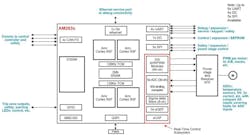
MCUs designed specifically for advanced automotive application, such as Texas Instruments' Sitara series,5 integrate multiple 32-bit CPU or DSP cores with fast-coupled memory (FCM), analog interfaces, ASIL-D safety hardware, and a powerful set of hardware accelerators. These accelerators often include high-speed analog-to-digital converters (ADCs), analog comparators, buffered digital-to-analog converter (DACs), enhanced pulse-width modulators (EPWMs), enhanced quadrature encoder pulse generators, and sigma-delta filter modules (Fig. 3).
One example of this approach is an inverter developed by Hillcrest Energy Technologies, which unveiled in December 2022 a prototype of an 800-V, 250-kW ZVS inverter that uses SiC power transistors. Hillcrest’s inverter technology implements its ZVS switching scheme using novel control software algorithms running on microcontrollers.
The company says its soft switching technology nearly eliminates switching losses and allows the converter's switching frequency to be significantly increased. This results in much better performance while reducing the size of the dc-link capacitors used in the design by 15% or more.
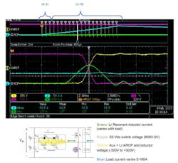
Pre-Switch is enjoying good success with its own unique, and more radical, approach to implementing ZVS soft-switching. They use an AI-based algorithm to generate switching control signals based on its best guess of what's needed, analyze the results in real-time, and then fine-tune the parameters for the next cycle. The technique, known as "Pre-Flex,"4 accurately controls the timing of small, relatively low-cost auxiliary resonant switches, which are combined with inductors and capacitors to ensure that ZVS or ZCS soft-switching continues, independent of changes in bus voltage or load currents (Fig. 4).
The company offers an evaluation platform for its CleanWave technology in the form of a fully functional 200-kW inverter with integrated motor control. It delivers a peak efficiency of 99.5% at 100 kHz and a power density of 210 kW/L. The technology section of Pre-Switch's website includes a video of the waveforms produced by a prototype inverter during its startup under unknown conditions. Subsequently, timing is optimized and other variables are adjusted to ensure that its pulse-width-modulated (PWM) input generates a clean current ramp to synthesize the first part of a sine wave.
References
1. “Soft-Switching EV Traction Inverter Exploiting Full Potential of Wide Bandgap Devices,” Philip Korta, Lakshmi Varaha Iyer, and Narayan C. Kar, 2020. IEEE, Document # 978-1-7281-5414-5
2. “SiC-Based Inverter Improves Efficiency in EVs, Renewables,” Maurizio Di Paolo Emilio , EE Times, October 24, 2022.
3. “Analysis and Evaluation of Soft-switching Inverter Techniques in Electric Vehicle Applications,” Wei Dong, Virginia Tech, 2003.
4. “The Operation of Auxiliary Resonant Commutated Pole (ARCP) and its Benefits for Electric Motor Drives,” James Hamond, Derek Kroes, Bruce Renouard, and Nigel Springett, Pre-Switch Inc. 2021.
5. “Design Priorities in EV Traction Inverter with Optimum Performance,” Xun Gong, Texas Instruments, 2023.
About the Author
Lee Goldberg
Contributing Editor
Lee Goldberg is a self-identified “Recovering Engineer,” Maker/Hacker, Green-Tech Maven, Aviator, Gadfly, and Geek Dad. He spent the first 18 years of his career helping design microprocessors, embedded systems, renewable energy applications, and the occasional interplanetary spacecraft. After trading his ‘scope and soldering iron for a keyboard and a second career as a tech journalist, he’s spent the next two decades at several print and online engineering publications.
Lee’s current focus is power electronics, especially the technologies involved with energy efficiency, energy management, and renewable energy. This dovetails with his coverage of sustainable technologies and various environmental and social issues within the engineering community that he began in 1996. Lee also covers 3D printers, open-source hardware, and other Maker/Hacker technologies.
Lee holds a BSEE in Electrical Engineering from Thomas Edison College, and participated in a colloquium on technology, society, and the environment at Goddard College’s Institute for Social Ecology. His book, “Green Electronics/Green Bottom Line - A Commonsense Guide To Environmentally Responsible Engineering and Management,” was published by Newnes Press.
Lee, his wife Catherine, and his daughter Anwyn currently reside in the outskirts of Princeton N.J., where they masquerade as a typical suburban family.
Lee also writes the regular PowerBites series.
