Improve The Design Of Your Passive Wideband ADC Front-End Network
As converter technology improves, so does the demand to resolve very high intermediate frequencies (IFs) accurately at high speeds. This poses two challenges: the converter design itself and the front-end design that couples the signal content to the converter. Even if the converter itself is excellent, the front end must be able to preserve the signal quality too.
High-frequency, high-speed converter designs exist in many applications, with wireless infrastructure and instrumentation pushing these boundaries. These applications demand high-speed, 100-Msample/s+ converters with resolutions of 12 to 16 bits. (“Wideband” represents the use of signal bandwidths greater than 100 MHz and ranging into frequencies of 1 GHz and above.)
FRONT-END BACKGROUND
“Front end” implies a network or coupling circuit (Fig. 1) that connects the last stage of the signal chain (usually an amplifier, gain block, or tuner) and the converter’s analog inputs. This assumes everything in the preceding signal chain circuitry has the proper bandwidth to support the frequencies to be resolved.
1. In this context, a front end is a coupling circuit between the last stage of the signal chain and an ADC's inputs. Besides providing sufficient bandwidth, it needs high linearity, good balance, and proper layout.
This last stage, or front-end circuit, also needs to have the proper bandwidth, but there is more to it than that. It must also be very linear, well balanced, and properly laid out on the printed-circuit board (PCB) to preserve the signal content properly. If not, the converter will pick up these nonlinearities imposed by the front end, which show up as distortions and noise in the frequencies of interest. The front-end network has to be carefully designed to meet the demands of any high-speed, high-resolution converter.
Typically, there are two types of front ends: passive and active. Active front ends use an amplifier or “gain block” to drive the signal into the converter’s analog inputs. These front ends are generally easier to design with as long as the proper amplifier is chosen. But when very high frequencies are required for the design, amplifiers tend to be performance limited, in linearity terms, to 200 MHz. In fact, some wideband amplifiers have usable bandwidths of greater than 200 MHz, but they tend to be high in power consumption.
TRANSFORMERS: SPECS, TOPOLOGIES, AND TYPES
The transformer, which can imply a flux coupled transformer topology, is inherently ac-coupled, since it is galvanically isolated and will not pass dc levels. It provides a quick and easy way of translating from a single-ended to a differential circuit, which is the common analog input interface for converters. A center-tapped transformer provides the freedom to set the common-mode level arbitrarily. This combination of virtues reduces component count in front-end designs, where it is critical to keep complexity at a minimum.
Care should be taken when using center-tapped transformers. If the converter circuit presents large imbalances between the differential analog inputs, a large amount of current could flow through the transformer’s center tap, possibly saturating the core. For example, instability could result if the VCM/CML pin is used to drive the center tap of the transformer and a full-scale analog signal overdrives the converter’s input, turning on the protection diodes.
The transformer also provides basically noise-free gain, which depends on the designer’s choice of turns ratio. Signal gain is ideally equal to the turns ratio of the transformer. Although voltage gains are inherently noise-free, using a transformer with voltage gain does gain the signal noise as well as tradeoff bandwidth.
A transformer should be seen simplistically as a wideband passband filter with nominal gain. The more gain in the transformer, the less bandwidth. Finding a 1:4 ratio transformer with low insertion loss performance in the gigahertz region is difficult today.
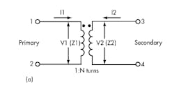
Although simple in appearance, transformers should not be taken lightly. A couple of brief equations relate the currents and voltages occurring at the terminals of an ideal transformer (Fig. 2a). When a transformer steps up voltage, its impedance load will be reflected back to the input.
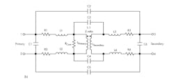
2. The ideal transformer and its equations (a) are straightforward. But inherent and parasitic departures from the ideal play parts in establishing a real-life transformer's frequency response and linearity (b)
The turns ratio, a = N1/N2, defines the ratio of primary voltage to secondary voltage. The currents are inversely related (a = I2/I1), and the ratio of the impedance seen in the primary reflected from the secondary goes as the square of the turns ratio (Z1/Z2 = a2). The transformer’s signal gain is expressed simply as 20 log (V2/V1) = 20 log/(Z2/Z1), so a transformer with a voltage gain of 3 dB would have a 1:2 impedance ratio.
A host of inherent and parasitic departures from the ideal comes into play with a transformer (Fig. 2b). Each has a role in establishing the transformer’s frequency response and linearity. These departures can help or hinder performance, depending on the front-end implementation. Figure 2b provides a good way to model a transformer to get first-order expectations about bandwidth response, insertion loss, and return loss.
Linearity models of the transformer are more difficult to come by and develop. Understanding the ferrite linearity is key when developing a model of this type, which still presents a handful of unknowns. Some manufacturers may provide modeling information, either on their Web site or through a support group. Designers planning to perform the model analysis using the hardware will need a network analyzer and a handful of samples to make all of the measurements properly. However, neither of these methods will divulge all linearity insights other than phase and amplitude imbalances, which can commonly cause even order distortions.
All real transformers have losses and limited bandwidth. As the configuration of parasitics implies above, one can think of a transformer as a wideband bandpass filter, which can be defined in terms of its –3-dB points. Most manufacturers will specify transformer frequency responses in terms of the 1-, 2-, and 3-dB bandwidth. A phase characteristic accompanies the amplitude response. Usually a good transformer will have a 1% to 2% phase imbalance over its frequency passband.
The transformer’s insertion loss, or the loss over the specified frequency range, is the most common measurement specification found in any transformer datasheet. Return loss is the transformer’s mismatch of the effective impedance of the secondary’s termination as seen by the primary.
For instance, if the square of the ratio of secondary to primary turns is 1:2, one would expect a 50-Ω impedance to be reflected onto the primary when the secondary is terminated with 200 Ω. However, this relationship is not exact.
For example, the reflected impedance on the primary changes with frequency. First, find the return loss at the center frequency specified for the design. This example uses 110 MHz. Zo is found not to be 50 Ω as assumed for an ideal transformer. It is lower, as found in Equation 3:
Return loss (RL) =
–18.9 dB @ 110 MHz =
–20*log((50 – Zo)/(50 + Zo)) (1)
10^(18.9/20) = ((50 – Zo)/(50 + Zo)) (2)
Zo = 39.8 Ω (3)
Ratio the primary Zo result in Equation 3 and the secondary ideal impedance, 200 Ω in this case. Do the same for the primary ideal (50 Ω) and solve for the real secondary impedance:
Z(primary reflected)/Z(secondary ideal) = Z(primary ideal)/
Z(secondary reflected) (4)
39.8/200 = 50/X (5)
Solving for X:
X = 251 Ω (6)
The secondary needs to have a 251-Ω termination when using a 1:2 turns-ratio transformer. Therefore, using a higher termination accounts for the core losses inside the transformer, yielding not only a better match, but also an improved input drive on the primary side of the transformer.
Having an improved input drive implies less power is required to reach the converter’s full-scale input. In general, as the impedance ratio goes up, so does the variability of the return loss. Keep this in mind when matching the front-end design of the preceding stage with any transformer.
Amplitude and phase imbalance are two of the most critical performance characteristics when considering a transformer or balun. These two specifications give the designer some perspective on how much linearity to expect when a design calls for high (above 100 MHz) IFs.
As the frequency increases, the nonlinearities of the transformer also increase, usually dominated by phase imbalance, which translates to even-order distortions (mainly second harmonic) as seen by the converter. Don’t be quick to blame the converter, though. Look at the front-end design or transformer first if the expected spurious is way off.
Imbalance (Fig. 3) is important. Consider the input, x(t), to the transformer. It is converted into a pair of signals, x1(t) and x2(t). If x(t) is sinusoidal, the differential output signals, x1(t) and x2(t), are of the form:
3. A mathematical analysis in the text, based on this simple ADC model, helps explain why transformer nonlinearity rises with imbalance.
The analog-to-digital converter (ADC) is modeled as a symmetrical third-order transfer function:
Then:
IDEAL CASE: NO IMBALANCE
When x1(t) and x2(t) are perfectly balanced, they have the same magnitude (k1 = k2 = k) and are exactly 180° out of phase (Φ = 0°). Since:
Applying the trigonometric identity for powers and gathering terms of like frequency:
This is the familiar result for a differential circuit. Even harmonics cancel for ideal signals, while odd harmonics do not.
MAGNITUDE IMBALANCE
Now suppose the two input signals have a magnitude imbalance, but no phase imbalance. In this case, k1 ≠ k2, and Φ = 0:
Substituting Equation 7 in Equation 3 and again applying the trigonometric power identities in Equation 14 . We see from Equation 8 that the second harmonic in this case is proportional to the difference of the squares of the magnitude terms, k1 and k2, viz:
PHASE IMBALANCE
Assume now that the two input signals have a phase imbalance between them, with no magnitude imbalance. Then, k1 = k2, and Φ ≠ 0:
Substituting Equation 10 in Equation 3 and simplifying, we get Equation 17.
(17)From Equation 17, we see that the second harmonic amplitude is proportional to the square of the magnitude term, k:
A comparison of Equation 15 and Equation 18 shows that the second-harmonic amplitude is more severely affected by phase imbalance than by magnitude imbalance. For phase imbalance, the second harmonic is proportional to the square of k1. For magnitude imbalance, the second harmonic is proportional to the difference of the squares of k1 and k2. Since k1 and k2 are approximately equal, this difference is small.
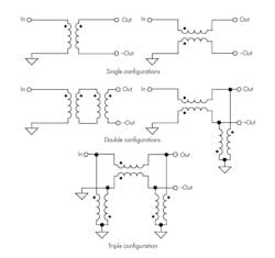
Higher-order turns or impedance ratio transformers have a lower tolerance to imbalance. If the “right” transformer cannot be found and linearity is an issue for the application, try using multiple transformers or baluns in a cascaded fashion. By employing a second transformer, second-harmonic distortions usually decrease because the second transformer acts to rebalance the previous signal converted from single-ended to differential on the first transformer.
Two or, in some cases, three transformers can be used to help convert the single-ended signal to differential (Fig. 4) more adequately across high frequencies. The downside of using this method is the increased PCB space, higher cost, and higher insertion loss (i.e., higher input drive). New high-frequency transformers are on the market today. Anaren’s patented design uses a coreless topology allowing for extended bandwidth in the gigahertz region that only employs a single device.
4. Multiple transformers can be used in various configurations for single-ended to differential conversion.
Not all transformers are specified the same way by all manufacturers, and transformers with apparently similar datasheet specifications may perform differently in the same situation. The best way to select a transformer for the design is to collect and understand the specs of all transformers being considered and request any key data items not stated on manufacturers’ datasheets. Alternatively, it may be useful to measure their performance using a network analyzer.
WIDEBAND CONSIDERATIONS
Understanding the transformer and its specifications provides a great starting place for figuring out how the front end is going to perform in the end. Essentially, three other metrics need to be thought about when designing a wideband network as well: bandwidth, matching, and the PCB layout itself. Each is important and can play a pivotal role in achieving the best performance required by the front end.
While the transformer has a specified bandwidth, the front-end design can limit the actual bandwidth provided because inherent PCB and internal ADC parasitics tend to roll off the transformer early. Some designs may require more bandwidth than actually measured, even though the transformer bandwidth was selected appropriately. From the converter’s standpoint, there is still plenty of bandwidth. But from the front-end design, this could be limited or extended depending on the topology used.
One way to extend the bandwidth of the transformer is to place low-Q inductors or high-frequency ferrite beads in series (LS) with each of the converter’s analog inputs (Fig. 5).
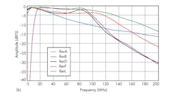
5. Low-Q inductors or high-frequency ferrite beads in series (LS) with a converter's analog inputs can extend bandwidth (a). However, this can affect passband ripple (b.) The "baseline" measurement was performed with no inductor.
Passband flatness can change, and it needs to be re-evaluated with this technique. Figure 5b shows results of different value inductors versus bandwidth. In the baseline results, no LS is present.
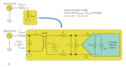
Matching the front end (Fig. 6) can imply a couple of things, depending on the designer’s viewpoint. By definition, it simply means that a certain source and load resistance (usually 50 Ω) has been defined for the front-end network and should be equal. This yields the maximum signal power transfer between the source and the load to minimize reflections.
6. Matching means more than defining an ohmic impedance and matching it across source and load (a.) To achieve maximum signal power transfer implies optimization over the band of interest. (b.)
Usually, this takes the form of a complex conjugate match since the converter’s internal input impedance is complex, as well as the transformer’s non-idealities in the front-end network design. The source is defined as the preceding stage before the front-end network. The load will encompass the front-end network. This includes the transformer, any termination or filtering between the secondary of the transformer and the analog inputs of the converter, and the converter’s complex input impedance.
Matching also relates to bandwidth. As the bandwidth rolls off on the front end, it is a good indication that the equal source to load is moving apart. Matching the front end over the intended bandwidth gives rise to preserved performance through many specifications, not just dynamic performance, i.e., signal-to-noise ratio (SNR) and spurious free dynamic range (SFDR). This is particularly important at higher frequencies since front ends tend to roll off quicker as discussed.
A particular front end was designed to have a pass-band region from 10 to 70 MHz using a 1:9 impedance ratio transformer with a datasheet bandwidth specification of 250 MHz. Going through the various tradeoffs, many different approaches can be used to achieve the boundary conditions for the design.
Often, only one design will work or be the best choice. In this example, REVL was chosen because it has the best “match” over the specifications required for the design. The design meets the dynamic spurious performance above 85 dB. It also has the best input impedance match over the entire band of interest, allowing for 92% of the signal power to be transferred to this network while maintaining a passband flatness specification below 1 dB.
The term “matching” can be used loosely. However, it really implies optimization over the band of interest given a set of defined performance parameters for the front-end network.
Layout is another variable that can wreak havoc on any front-end design, particularly at high frequencies. Improper layout can mess up the front-end design, causing unexpected performance. Don’t undo all the hard work done to define the front end. Take the time to keep the layout sound and symmetrical.
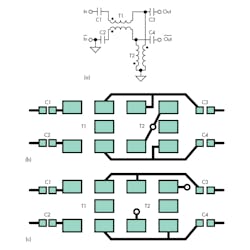
One example using multiple transformers in cascade (Fig. 7) as described can keep the even order distortions at bay. The two layout diagrams depict small differences between the layouts of two transformers used in front of the ADC. One layout (b) performs better over a wide band of frequencies, though. It is more symmetrical and forces return currents or ground references to be common.
7. The same cascade of transformers (a) yields different results depending on how symmetrically the traces are routed on the PCB (b and c).
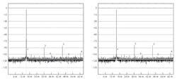
Proof can be seen in the fast Fourier transform (FFT) performance plot (Fig. 8) measurements of an AD9268, 16-bit, 125-Msample/s dual-channel ADC. Figure 8a was obtained using the symmetrical layout. It yielded a second harmonic of 85 dB with a 140-MHz IF applied at –1 dBFS. Figure 8b shows the performance under these same conditions with the non-symmetrical layout. The second harmonic was measured at 79.5 dB—a greater than 5-dB loss in performance!
8. The more symmetrical output arrangement of the upper transformers in 7b produced the spectrum on the left. Note that the second harmonic is 5 dB lower than in the non-symmetric design on the right.
FERRITE VERSUS NON-FERRITE
Traditionally, wire wound or ferrite transformers have been the solution of choice in converter front-end circuit design to convert the last stage of the signal chain’s signal from single-ended to differential with typical transformation impedance ratios of 1:1, 1:2, and 1:4. Wire wound topologies deliver good performance at frequencies below 200 MHz, where they exhibit good balanced phase and amplitude performance and good insertion and return loss.
However, wire wound baluns suffer from some drawbacks, the most serious of which is the deterioration of performance at higher frequencies. Wire wound baluns are essentially lumped element components that work well at lower frequencies, but whose performance deteriorates as the effects of parasitics become more pronounced at higher frequencies and ferrite losses increase.
By definition, lumped element components aren’t suited for use as the wavelength of operation becomes comparable to the physical dimensions of the component. However, Anaren offers a series of baluns that are non-ferrite coupled, microwave stripline structures and are inherently suited for operation at higher frequencies, i.e., above 200 MHz.
These baluns are coupled stripline designs that use softboard (PTFE/Teflon) material as the dielectric medium. The dielectric is typically low loss, keeping insertion loss to a minimum at higher frequencies. In addition, this technique allows a significant amount of circuitry to be packed into a package, minimizing package size and yielding up to 80% space savings over typical ferrite topologies.
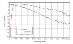
Unlike wire wound baluns, no ferrites are used in an Anaren balun structure (Fig. 9). Another advantage to non-ferrite transformer technology is its insensitivity to variations in differential impedances over wider bandwidths, which are common when using unbuffered ADCs that have a change in input impedance when the converter moves between the sample and hold domains. Any sensitivity on part of the balun or transformer to the converter’s impedances could reveal degradation in performance.
9. One can see a considerable difference in passband flatness using the same AD9640 125-Msample/s converter fed with a conventional ferrite balun and with an Anaren stripling balun.
When designing a wideband network in front of the ADC, choose the transformer and collect the specifications required to make the best selection for the application. In particular, keep imbalance performance in mind when choosing a transformer. Two or possibly three transformers may be required for the design as shown in the topologies above.
If extra bandwidth is required, use series low-Q inductors or high-frequency ferrite beads on the secondary of the transformer. But remember to re-evaluate passband flatness to make sure it is still in check. Matching over the entire band can be difficult. Matching should really encompass optimization of all specifications defined by the design to get the maximum power transferred to the front-end network.
On the layout side, don’t disregard symmetry on the front end or the performance may be mitigated. Finally, keep in mind that other solutions available today tackle some of the widest band applications, improving on passband flatness and dynamic performance at higher frequencies while saving PCB space.
About the Author

Rob Reeder
Application Engineer, High-Speed Converters, Texas Instruments
Rob Reeder is currently the application engineer for High-Speed Converters at Texas Instruments (TI) in Dallas. Rob’s prior experience includes RF design at Raytheon Missile Systems in Tucson, Ariz., including analog receivers and signal-processing applications. He was also a system application engineer with Analog Devices in the High-Speed Converter and RF Applications Group in Greensboro, N.C., for over 20 years.
He has published over 130 articles and papers on converter interfaces, converter testing, and analog signal chain design for a variety of applications. Rob received his MSEE and BSEE from Northern Illinois University in DeKalb, Illinois, in 1998 and 1996, respectively. When Rob isn’t writing papers late at night or in the lab hacking up circuits in the lab, he enjoys hanging around at the gym, listening to EDM, building rustic furniture out of old pallets, and, most importantly, chilling out with his family.


