So…LTspice of the K2-W Op Amp Reveals the Mad Scientists’ Fingerprints (Part 3)
What you’ll learn:
- The K2-W's first-stage differencing amplifier has greater gain than a diff amp.
- The use of “long tail” resistors is almost identical to using a current source.
- The K2-W produced sufficient performance using only two vacuum tubes to create a new market for commercial users of analog computers.
- How the K2-W was constructed by reviewing detailed photos with the case removed.
LTspice ain’t bad
You can’t cut/paste on your bench
So, simulate/learn
In this finale of the three-part series on the K2-W, we’ll use the schematic from Part 2 to run some LTspice simulations to gain insight on the K2-W's design. This schematic has the K2-W's first stage on the left half and a classical current-source and diff pair on the right (Fig. 1).
I “efficiently” did a preliminary LTspice run on the left half of the schematic to establish the average current in the coupled-cathodes’ resistor to −300 V DC. Then I created a current source with that same magnitude of direct current for our classical diff-pair amplifier on the right half of the schematic (the loads on both diff-pair halves are the same; I lazily—this time it was—combined the resistances into one resistor on the left triode of the diff amp).
Head Games
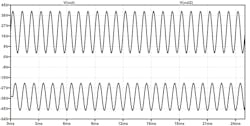
So that the output waveforms are visible in my plots, I created a second signal generator for the schematic’s right half circuit and shifted the 1-V p-p, 1-kHz input waveform by 250 µs (1/4 wavelength). Here’s where we get the forehead-slapper (Fig. 2).
Notice that both of our outputs are identically voltage-divided by a resistor-based output level shifter, so that actual amplifier-stage voltage gains are higher than what we see in the plot. The upper waveform, Vout, is the K2-W first stage output of about 36 V p-p while our classical diff-pair amp has a Vout2, the lower waveform, of about 24 V p-p.
Since we’d use both outputs, the diff amp would actually be superior in voltage gain at 48 V p-p had the next stage of the op amp been differential. However, in the K2-W, a single-ended amplifier is used in the third triode stage, followed by the fourth triode as a buffer stage—all of which are wonderfully detailed by both Walt Jung and Bob Pease.
Building a Philbrick Foundation
As we had discussed in Part 2, the funky cathode-follower/cascode-differencing (I’m not going to call it “differential”) input of the M9 gun director's op amp, as implemented in Philbrick’s K2-W op amp, gives us ~50% more voltage gain than a classical diff amp with an ideal current source. Cheaper, and higher gain, with good-enough CMRR because the 300-V DC supplies in an analog computer are rock solid. Nicely done, Philbrick.
Just one more thing on that K2-W input stage, to be thorough in its analysis, about the “long tail” resistor Voodoo between −300 V DC and the coupled cathodes mentioned by Walt. We know that a proper current source requires one or more active devices (yet more, costly, tubes as can be seen in Figure H-6 of Chapter H in Walt Jung’s book on Page H.22) to produce a “stiff” source. So, let’s have a look at what the coupled cathode resistor’s current looks like and explore it with a new schematic (Fig. 3).
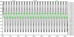
The output voltage for the left half of the schematic, the K2-W first stage, is the non-shifted ~36-V p-p sine wave in Figure 4. The coupled-cathodes’ resistor’s current is shown by the green waveform; its scale being on the right side of the plot.
Though there’s a perceptible sinusoidal current, looking at it more closely reveals that it only varies ±0.13% from its average current. Wut? Yes, it’s pretty stiff in terms of current variation. One beauty of LTspice is the ability to cut-and-paste (try that on a bench, Bob, lol) circuits and substitute an ideal current source for that long tail resistor, delay the signal by 250 µs in the circuit on the right half of the schematic, and run the simulation.
The output waveform is shown in the above plot as the delayed output waveform Vout2. You’ll notice that it’s identical to the long tail circuit’s output Vout. So, no additional tubes are needed, just add one resistor and get almost identical amplifier performance using a high-voltage, centralized, negative power supply. Nicely done, op amp forefathers.
Bench Work is Benched, For Now
My plan WAS to do some bench work with the K2-W, but my tubes haven’t arrived in time, so we’ll need to delay that effort for a bit. I also managed to pick up a couple more K2-Ws from overseas as I write this—having three op amps could make for some interesting analog computing and op amp fun here in future.
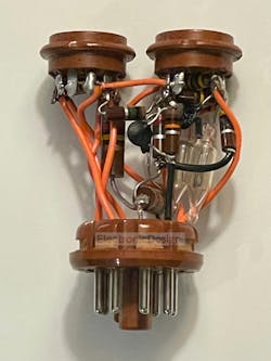
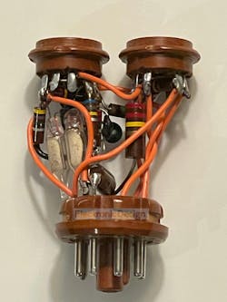
In Part 2's comment section (an interesting set of discussions got hatched there...), one of our readers volunteered some sweet photos he had taken of "K2-W guts" so we can all get a rare glimpse of what's inside and how the K2-W was built by the clever folks at Philbrick. Thanks to Professor Emeritus Stephen A. Dyer** of Kansas State University for allowing Electronic Design to publish his pics of the K2-W's innards:
Though I had to resort to Plan B by using LTspice, I think it gave us sufficient insight into how this critical functional block, the K2-W's first stage, was simplified, maximized in voltage gain, and most of all, was cheap enough to spit out like jellybeans to enable the design and construction of commercially affordable analog computers containing dozens, if not hundreds, of K2-W op amps.
Philbrick was genius in realizing that it was cost and simplicity (minimizing tube counts also increased reliability and decreased maintenance and troubleshooting costs), along with solid applications information, that would trigger a revolution in analog computing in the commercial world. A subsequent enabling of capability and products, including musical instruments, was triggered with the availability of cheap analog computers.
**Professor Dyer also noted exceptions to those values listed in the schematic shown in Part 1 of this series, based on removing the case and inspecting the K2-W closely. Those exceptions from what's in the schematic are noted in the BOM in bold as follows:
R2: 1.0M 0.5W 10%
R3: 220K 1W 5%
R4: 2.2M 0.5W 10%
R5: 470K 0.5W 10%
R6: 10K 0.5W 10%
R7: 220K 0.5W 5%
R8: 680K 0.5W 10%
R9: 4.7M 0.5W 10%
My K2-W LTspice simulations were completed a couple of weeks prior to this information coming in, and the Blog already went through my copy editor and the production process that gets all of this published and into our newsletters. What you see here with the revised edit and pics is a last-minute cowboy edit by me so that we stay on schedule to publish on Tuesday.
We'll be moving on to other things now, but will revisit K2-W later this year. Meanwhile, please feel free to leave comments below on your thoughts, experiences, and where you think we should take the K2-W from here.


