A series of new tests highlights the benefits of using an abrasive-loaded gel to clean probe tips.
Production wafer-level test is used to evaluate the performance of all manufactured ICs prior to packaging and assembly. Today�s newest memory, mixed-signal, digital, and microprocessor devices are electrically tested using a wide variety of probe-card technologies. A few examples include cantilever epoxy ring, vertical area array, MicroSpring�, and membrane.
Most fine-pitch wafer test applications use cantilevered epoxy-ring probe cards made with small-diameter probe needles. This method costs less than other technologies and generally provides faster cycle time while meeting device pad-to-pad pitch requirements.
For these cards, electrochemically tapered probes made from drawn tungsten, tungsten-rhenium (WRe), beryllium-copper, or palladium-alloy wire are brought in contact with the aluminum or copper bond pads. With sufficient forward tip displacement or scrub, electrical contact is made as the probes break through the contaminants and oxides on the pad surface.
For a successful test, the current must be delivered to the DUT at full overtravel; however, the quality of the electrical contact is critical. The current that flows between the probes and the bond pads is constricted to intermetallic contact areas or a-Spots and across any semiconductive films.
This contact quality dramatically affects the integrity of the test signal and can be quantified by the contact resistance (CRES). CRES varies inversely with the contact area; however, due to the dielectric properties of the bond-pad surface contaminants, the film resistance dominates the CRES magnitude and stability.2
Since the size of the plastically deformed bond-pad contact area is directly proportional to contact pressure, the tip shape also contributes to CRES. As such, the CRES of an actual probe depends on the bond-pad material, the amount of scrub, and the shape and condition of the probe tip.
For cantilevered probe cards, two types of probe-tip geometries are available: flat and radius. The flat or conventional tip is relatively easy to manufacture and maintain and the most commonly used.
During testing, these probes demonstrate a toe-to-heel tip rotation combined with a slide deformation parallel to the aluminum pad surface. After repeated touchdowns, pad materials and other contaminants mechanically adhere and accumulate on the probe-tip surface.
Eventually, these adherent materials cannot be removed from the contact region by the probe�s self-cleaning action. Instead, the adherent contaminants accumulate and overlap the electrical contact regions, substantially increasing the CRES.
Radius-tip probes improve CRES stability, reduce adherent material, and significantly decrease bond-pad damage.3 Until recently, cleaning procedures could easily damage this shape, and custom off-line cleaning procedures were necessary for maintaining the integrity of a radius-tip shape.
For fine-pitch devices, excessive probe damage on the bond pads can adversely affect packaging and assembly yields.4 Low and stable CRES is critical to avoid reprobing devices to confirm first-pass sort results.
The most common method of controlling CRES uses abrasive cleaning to physically remove the contaminants from the contact surface. For this type of cleaning, the probes are subjected to multiple touchdowns on lapping film with 0.5-, 1-, 3-, or 5-mm grit; a tungsten-carbide plate; or a ceramic block.
Each time the probes are cleaned, the tips are subjected to frictional shear stresses, and material is removed until the probes are out of specification. Particulates, bond-pad metal, or probe material left on the abrasive pad from the previous cleanings can adhere to the probe tips and redeposit on the wafer.
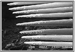
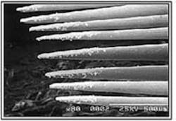
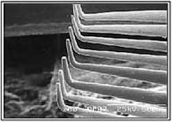
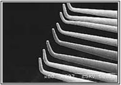
Unfortunately, many probe-card technologies developed for fine-pitch devices are built with materials that cannot withstand severe frictional shear loading or contact surface deformation against a burnishing pad. For these technologies, a nondestructive, low-impact cleaning technique that collects debris and cleans the contact surface is needed. The results of abrasive and nondestructive cleaning methods applied to cantilevered probes are compared in Figure 1.
Figure 1. Abrasive and Nondestructive Cleaning Methods Applied to a Tungsten-Rhenium, Cantilevered Epoxy-Ring Probe Card
Previous work on blanket aluminum wafers showed that it is relatively easy to break through the surface oxide layer and produce stable contact.5 Yet, when similar testing is performed on fab-processed test die, the same practices do not produce stable CRES and must incorporate some sort of cleaning process.
Two case studies were performed using processed test die wafers that evaluate the following:
- Probe-Tip Shape Effects�the comparison of the CRES behavior between flat-tip and radius-tip probes.
- Probe-Cleaning Optimization�the application of nondestructive cleaning methods to control CRES for fine-pitch devices.
From these two studies, methods for assessing incremental improvements in CRES stability were developed and applied to wafer-level test of fine-pitch devices.
Materials and Methods
For the experiments, epoxy-ring cantilevered probe cards designed for fine-pitch devices were built using small-diameter WRe flat-tipped probes and ECP� electrochemically polished probes with ~12.7-�m radius tips. The probe cards were built with best-known practices for use in a standard tester/prober setup on a high-volume production test floor.
Fab-processed 200-mm wafers with electrically shorted bond pads were probed at a 2-mil overtravel, and the CRES values between pin pairs at each touchdown were measured and recorded using a custom test program. On each wafer tested in this experiment, 535 test die were probed, and tip images were collected at 50-, 100-, 500-, and 1,000-touchdown intervals.
For Case 1, the probes were not cleaned throughout the entire test. For Case 2, probe cleaning was performed using two grades of nondestructive cleaning media: Probe Polish� 201 and Probe Polish 210 provided by International Test Solutions.
Case Study 1: Probe-Tip Shape Effects
For the flat-tipped probes, many researchers have shown that the initial CRES is fairly low; however, within a few touchdowns on the test die, the CRES becomes unstable. In a production environment, this sort of CRES instability would result in frequent cleaning of the probes or multiple reprobes to avoid unnecessary probe yield loss. In comparison to the flat-tip probes, radiused probes demonstrate a more stable CRES across the wafer.5
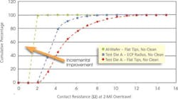
Time-based scatter plots are useful for assessing CRES stability and providing cleaning frequency guidelines; however, incremental improvement or degradation in CRESRES provide a relatively straightforward way of assessing small performance changes; for example, the ogive shape reflects the level of instability during testing. behavior is very difficult to assess. Cumulative frequency distributions of C
In Figure 2, the CRES frequency distributions from test die are compared to that of a blanket aluminum wafer. For the aluminum wafer (green) with no cleaning, 100% of the probes had CRES <5 W. Of the test die probed with flat tips (red), 70% of the die had CRES <5 W; and of those probed with ECP radius tips (blue), 90% had CRES <5 W. In this experiment, when the CRES exceeds 5 W, the test die is arbitrarily judged as defective. As a result, ~30% probe yield fallout due to CRES instability would have occurred with the flat-tip probes. In contrast, the yield fallout associated with the radius-tip probes would have been ~10%.Figure 2. Comparison of CRES Variations for Test Die Against Aluminum Wafer
Flat and radius probe-tip contact mechanics are modeled in Figure 3a and Figure 3b. Oxidized aluminum and contaminants exist on the bond-pad surface, and when probing with a flat tip, the CRES fluctuations are attributable to repetitive material adhesion, accumulation, and removal from the electrical contact region.3 With repeated touchdowns, the region of adherent material increases in size and overlaps the electrical contact region (Figure 3c). It is important to note that on a blanket aluminum wafer, the overlapped contact regions typically do not have significant effects on the CRES.5
| Probe-Tip Contact Model | Contact Surface | Probe Mark on Aluminum Pad |
Figure 3. Comparisons of Flat and Radius Probe Tips
(a) Models of flat and (b) radius probe-tip contact mechanics.5 The adherent material and the electrical contact regions of the overlap on the heel of the flat-tip probe surface (c) and are separated on the radius probe surface (d). The overall size of the scrub mark from the flat-tip probe (e) is substantially larger than that of the radius probe (f).
For a radius tip, the rounded-tip geometry allows the aluminum to deform smoothly around the contact surface and yields smaller probe marks (Figure 3b). With repeated touchdowns, the adherent material collects at the rear of the probe and away from the electrical contact region at the leading edge (Figure 3d). As a result, electrical contact is made across a relatively clean surface, and the CRES tends to be stable.
Similar work demonstrated stable CRES for a tip radius of 7-mm <22-mm.3 Others have reported reduced material adhesion and increased die touchdowns between cleanings using a rounded probe-tip geometry.6 These results indicate that it is possible to maintain relatively stable CRES with a radiused, smooth probe tip by reducing the amount of adherent bond-pad materials on the contact surface.
Particles and worms generated during probing also can detrimentally affect probe yield. For that reason, a cleaning methodology that collects the debris is necessary to maintain high probe yields.7 As a result, radiused probes with a proper cleaning regimen could provide a substantial reduction in the cost of ownership.
Case Study 2: Probe Cleaning Optimization
AMI Semiconductor currently uses flat-tip probes for wafer sort. As such, the work in Case 2 focused on controlling CRES using methods directly applicable to the existing test-floor process as well as fine-pitch testing.
As in Case Study 1, within a few touchdowns, the CRES readings on the test die become increasingly unstable. If this were an actual device, an online cleaning operation using 3-�m grit lapping film or a tungsten-carbide plate would be performed after 100 touchdowns to remove adherent contaminants. However, for this case study, a nondestructive cleaning approach was used to control the CRES without damaging the probe tips and compromising the planarity and alignment of the probe card.
Probe-card cleaning was performed online using PP201 and PP210. These cleaning materials are composed of a highly processed, nontoxic polymer impregnated with abrasive particles. The suspended particles remove adherent contaminates from the contact area and sides of the tip without damaging the probe surface. The polymeric gel effectively encapsulates and collects the loosely attached debris.7
The cleaning material was attached to the standard prober cleaning unit. During each cleaning cycle performed every 100 touchdowns, the probe card was overtraveled into the cleaning material ~150 �m.
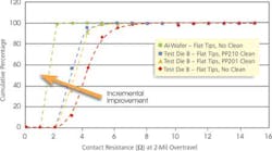
Initially, PP201 was used, and CRES stability improvements were observed. This material, however, was unable to properly scrub the entire probe contact surface and remove the adherent bond-pad material. As a result, some CRES instability, albeit significantly improved from the initial or no-clean results, occurred.
Cleaning with PP210, which has larger abrasive particles, was implemented, and the contaminants from the outer edges of the probe tip as well as the entire probe contact surface were removed. As such, the probe contact surface was relatively clean, and the CRES behavior was substantially more stable.
For this set of experiments, 4-W pass/fail limits were implemented. On the aluminum wafer, 100% of the probes had CRES of less than 4 W . Under this criteria, the estimated test-die probe-yield loss for flat-tip probes with no cleaning is ~42% (red), probes cleaned with PP201 is ~7% (yellow), and those cleaned with PP210 is ~3% (blue) (Figure 4).
Figure 4. Implementation of Two Nondestructive Cleaning Methods
Implementation of a nondestructive cleaning methodology was found effective for reducing contaminant and debris-related CRES instability. The results indicate probe-card maintenance can be reduced while the overall probe-card service life can be extended.
Summary
A systematic test methodology was designed using best-known practices and applied to understand the CRES characteristics of developing a fine-pitch device. In Case Study 1, incremental improvements in the CRES behavior that resulted from the probe-tip shape were quantified using normalized methodologies. A relatively stable CRES was obtained with a smooth radius-tip probe, which effectively produced a clean electrical contact between the probe tip and the aluminum bond pad. The recent developments in nondestructive media and cleaning practices facilitate online use of this fragile probe shape.
In Case Study 2, several nondestructive cleaning methods were incorporated to substantially reduce the CRES variance of the flat-tip probes. Low and controlled CRES variance consistently lends confidence to first-pass probe results, even if the CRES has an upward trend, and diminishes the need to reprobe the same pads multiple times.
With an optimized, nondestructive cleaning methodology, the service life of the probe card will be extended and the overall cost of ownership reduced. Currently, work is underway to develop a combination of tip-shaping techniques and online, nondestructive cleaning procedures to improve test throughput and increase probe card life when testing fine-pitch devices.
Acknowledgements
The authors would like to acknowledge Clint Churchill, Vail McBride, Kelly Burnside, Christie Jones, and Bob Pasley of AMI Semiconductor for their contributions in the completion of this work. In addition, the sponsorship from the respective organizations is duly recognized.
References
1. Broz, J. and Rincon, R., �Probe Contact Resistance Variations During Wafer Level Test,� IEEE International Test Conference, 1999.
2.Holm, R., Electrical Contacts, Springer Verlag, 1967.
3.Maekawa, S., et al., �Highly Reliable Probe Card for Wafer Testing,� IEEE Electronic Components and Technology Conference, 2000.
4. Hotchkiss, G. et al., �Effects of Probe Damage on Wire Bond,� IEEE Electronic Components and Technology Conference, 2001.
5.Stalnaker, S., et al., �Controlling Contact Resistance with Probe Tip Shape and Cleaning Recipe Optimization,� IEEE Southwest Test Workshop, 2003.
6.Haga, T., et al., �The New Probe Tip Fabricated by MEMS (LIGA Process) for No-Cleaning Test,� IEEE Southwest Test Workshop, 2003.
7.Humphrey, G., �Probe Card Online Cleaning,� IEEE Southwest Test Workshop, 2000.
About the Authors
Jerry Broz, Ph.D., is a senior applications engineer at International Test Solutions and the former director of research and product development at Point Technologies. Previously, he was a member of the group technical staff with the Worldwide Probe Development Team at Texas Instruments. Dr. Broz holds several patents and has written numerous publications in the areas of wafer-level test and IC packaging. He earned a Ph.D. in mechanical engineering from the University of Colorado. 303-885-1744, e-mail: [email protected]
Scott Stalnaker is a sort process engineering technician at American Microsystems, Semiconductor. He has two associate degrees in electronics from Idaho State University. AMI, Semiconductor, 2300 Buckskin Rd., Pocatello, ID 83201, 208-233-4690, ext. 6414, e-mail: [email protected]
Gene Humphrey joined International Test Solutions in 1997 to direct development of nondestructive cleaning materials for probe cards. Mr. Humphrey has 20 years experience as a research engineer and several patents. He graduated from the University of Wyoming with a B.A. in mechanical engineering. 925-606-0445, e-mail: [email protected]
International Test Solutions, 2479 Chardonnay Way, Livermore, CA 94550
Return to EE Home Page
Published by EE-Evaluation Engineering
All contents � 2004 Nelson Publishing Inc.
No reprint, distribution, or reuse in any medium is permitted
without the express written consent of the publisher.
