Today’s DMM designs are all about increasing a test system’s capability to comprehensively address diverse applications. For example, because DMMs already need to make isolated measurements, several manufacturers have added isolated digitizer functionality. This means that the same module can accomplish data acquisition and logging as well as conventional DMM measurements. In another case, DSP-based algorithms are performing RMS computation, but this is just one of the many signal processing jobs that a DSP can do.
In the process of developing DMMs beyond their basic measurement roots, trade-offs must be made. Very high measurement resolution and accuracy generally imply slower speed. High speed and high input impedance often attract more noise. And, safety clearances and maximum voltage ratings come under greater scrutiny as a module’s component density increases to accommodate new features. A manufacturer’s emphasis on certain application areas determines how these and many other performance issues will be balanced in a new design.
Changing the name
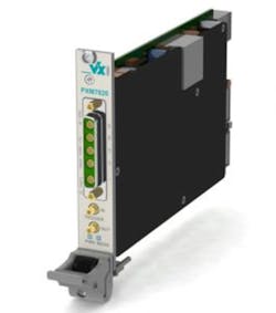
To better describe the mix of capabilities in its PXMe7820 (PXIe interface) instrument, VX Instruments calls it a high-speed multimeasurement device. The company’s Christian Plötz, technical sales engineer, explained, “Our philosophy is to have a digitizer that also is able to be a DMM. So we are thinking in MS/s. [Most] manufacturers of DMMs design a DMM and update the device with digitizer functionality, so they are thinking in reading/s.”
The PXMe7820 functions as a 40-MS/s, 16-bit high-speed digitizer that can handle 250-V peak signals and has a 5-MHz bandwidth. In addition, it is a fully isolated 24-bit resolution DMM that measures inductance, capacitance, and two- and four-wire resistance as well as the usual AC and DC voltage and current. As shown in Figure 1, the typical front-panel banana jacks have been replaced by coaxial connectors to handle high-speed signals.
Courtesy of VX Instruments
“Our customers often have the need to realize shorter test times to generate a higher product throughput,” Plötz said. “The PXMe7820 therefore combines high-speed measurement and the high-speed interfacing of PXIe. Furthermore, the combination of different functions in one device reduces the need for additional elements such as cabling and matrix units in the test setup. This also can reduce the test times of the application. Moreover,” he continued, “there is a rising demand for measurement devices that have a minimum influence on the measured signal. That is why we focused on high input impedance.”
VX Instruments produces a number of digitizers, power supplies, source-measure units, arbitrary waveform generators, and DMMs. Plötz said that the company’s experience gained through its digitizer and power supply designs was especially helpful when developing the multimeasurement PXMe7820. In particular, he said, the very low-noise and low capacitance to ground of the power supplies that drive the isolated measurement circuitry are key to high AC accuracy.
Pickering Interfaces distributes the PXMe7820 in the United States.
Emphasizing measurement accuracy
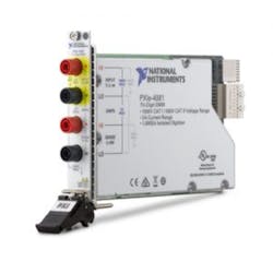
Courtesy of National Instruments
National Instruments’ PXIe-4081 DMM (Figure 2) follows on from the earlier PXI-4071 model and continues to focus on measurement accuracy. Several factors such as long-term stability, built-in calibration standards, and good thermal design contribute to measurement accuracy.
Basic inductance and capacitance measurements are not included in the 4081. Instead, they are available on NI’s PXIe-4082, a 6½-digit instrument with reduced specifications compared to the 4081: 1-A maximum current rather than 3 A, 300-V maximum voltage rather than 1,000 V, and 25 ppm of reading + 6 ppm voltage accuracy on the 10-V range vs. 12 ppm + 0.5 ppm.
According to Mike Watts, product manager-modular instruments at the company, “The PXIe-4081 7½-digit DMM builds on the technology used in the PXI-4071 DMM, using a unique combination of off-the-shelf high-speed ADC technology and a custom-designed sigma-delta converter to provide the noise, linearity, and speed performance required to achieve high-speed and high-precision measurements in a single instrument. Additionally, the PXIe-4081 DMM uses one of the most stable onboard voltage references available, Linear Technology’s LTZ1000 Ultra Precision Reference, to provide stable performance across temperature and time.”
Having an accurate onboard voltage reference certainly makes calibration convenient, but including a good reference and actually achieving the best possible performance from it are two different things. The LTZ1000 datasheet identifies some of the possible pitfalls.
Small temperature differences can generate error voltages that are significant compared to the reference’s basic specifications. One way this occurs is through the thermocouples formed when the device’s Kovar leads are soldered to copper PCB traces and via the thermocouples inherent in resistors and other associated components. In addition, mechanical stresses caused by temperature differences or because of the way a PCB has been mounted can change the reference output.
A design that successfully avoids degrading the voltage reference accuracy provides several benefits. Obviously, the DMM accuracy can be directly linked to that of the reference. Beyond that, a reference with long-term stability implies that a DMM requires less frequent external calibration. In a white paper, NI stated that, “… the PXIe-4081 includes a two-year guaranteed accuracy of 12 ppm to further reduce the cost of test by minimizing downtime for instrument calibration.”1
The PXIe-4081 also uses advanced DMM measurement techniques such as offset compensated Ohms and higher-order DC noise rejection.
Ohms
The Ohms function in the 4081 forces a current through the unknown resistance and measures the resulting voltage drop across it. Many applications involve not just the resistance in question, but also an accompanying voltage source. Examples given in an NI technical note include switching systems using uncompensated reed relays with Kovar leads (because of the Kovar-copper thermocouple voltage), in-circuit measurements on live power supply conductors, and measuring the resistance of batteries or forward-biased diodes.2
Offset Ohms compensation operates by measuring the voltage across the unknown resistance one time without any test current and again with test current. In the first measurement, any voltage that is measured is caused by an associated voltage source. Subtracting that value from the second reading effectively eliminates the voltage source from the measurement.
The technique works well but does have limitations. In the technical note, NI cautions against trying to eliminate offsets larger than 1 V. The offset Ohms compensation mode is intended for use when measuring low resistance values that usually produce a small test voltage. Because the test voltage is small, thermal EMFs can have a significant effect on accuracy.
Noise
Noise rejection typically focuses on reducing contributions at the AC supply frequency and its harmonics. One of the advantages of a sigma-delta converter, such as is used in the PXIe-4081, is the noise reduction it provides by bandwidth shaping. As noted in an EE-Evaluation Engineering special report, Analog Devices’ Walt Kester explained that in a sigma-delta ADC, the modulator shapes the noise, ”… so that it lies above the passband of the digital output filter, and the ENOB [effective number of bits] is therefore much larger than would otherwise be expected from the oversampling ratio.”3
Interestingly, Linear Technology recently released a 24-bit successive approximation ADC that operates at a 2-MS/s rate and includes an integrated digital filter capable of performing up to 65,536 averages.4 With this number of averages, the company claims the output achieves a 30.5 reading/s rate with less than 1 LSB of noise at a full 24-bit resolution. Of course, it takes more than an ADC to make a DMM, but it is important that sigma-delta ADCs no longer are the only path to high resolution.
The PXIe-4081 digital output filter provides additional noise reduction, and in the 4071, three selections are available. Normal DC noise rejection implements a digital filter with equal weighting for all samples. This means that transmission nulls occur at frequencies that are integer multiples of the inverse of the ADC aperture period. For example, specifying a 20-ms aperture corresponds to nulls at 50 Hz, 100 Hz, 150 Hz…. This type of noise rejection is similar to that used in DMMs with conventional dual-slope ADCs that typically measured for a number of power line cycles.
Second-order DC noise rejection creates nulls only at even multiples of the inverse of the aperture period, but the nulls are wider and the overall response falls off faster with frequency than for normal DC rejection. This means that the aperture time must be twice as long as with normal DC filtering to attenuate the same frequencies.
Finally, high-order DC noise reduction provides more than 100 dB of rejection for frequencies greater than about 4.5/aperture time. Using the same 50-Hz example, the aperture time must be at least 90 ms. The high-order filter has the benefit of very large attenuation for any frequency higher than 4.6/aperture time, but it does significantly reduce the readings/s rate.
Addressing field operation
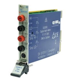
Marvin Test Solutions’ (MTS) Mike Dewey, director of marketing at the company, positioned the MTS GX2065-M DMM (Figure 3) as, “… a rugged, extended temperature version of the GX2065 DMM. Developed to address the demanding environmental conditions associated with portable/flightline test applications, the GX2065-M retains the same features and capabilities as the GX2065 but extends the operating and storage temperature ranges. Specifically, the GX2065-M is designed to operate from -20°C to +70°C.”
Courtesy of Marvin Test Solutions
Several of the trade-offs associated with the GX2065 design are discussed in a 2012 Autotestcon paper.5 Rather than using the 22-bit DC path, AC measurements are made by the 3-MS/s, 16-bit isolated digitizer. This approach allows a large number of samples to be acquired for each RMS calculation. The exact details of the RMS algorithm aren’t available, but it obviously increases resolution from the basic 16 bits of each sample to the 6½ digits (22 bits) quoted in the datasheet.
As the paper describes, “The DMM returns raw measurements and stores correction values internally as 64-bit fixed-point integers. Every DMM measurement requires at least the multiplication of two 64-bit integers and the division of the result by a 64-bit integer. The multiplication … can be done easily and quickly in software, [and] … takes only about 100 clock cycles…. However, … to speed up the [divide] computation, a custom 128-bit by 128-bit division peripheral was created in Verilog and instantiated in the FPGA.”
In another example of hardware/software trade-offs, “… logic-based state machines were implemented wherever possible, with interrupts used for servicing the various measurement and communication events.” This approach allowed most tasks to be handled outside of the main processor, such as, “… communicating across the isolation barrier, transferring data to the PCI bus, and reading the PWM outputs from the temperature sensors.”
The paper highlights some of the design considerations necessary to support the wide operating temperature range: “For high-temperature operation, careful layout and board cuts are required to minimize self-heating effects…. The PXI DMM uses the LM399 voltage reference, which includes a built-in, automatically controlled heater. For high-temperature operation, the heater’s power dissipation isn’t a problem because it automatically reduces its power consumption. However, at low temperatures, the heater must use the maximum amount of current to bring the voltage reference up to temperature.”
MTS solved the problem of a large current load at start-up by carefully sequencing the power supplies. Only after all of the supplies are operating and the voltage reference is near its final temperature are the analog supply regulators enabled. As the paper explains, “The complete sequence requires about 10 s at room temperature but can require up to 1 minute at -20°C.”
Dewey concluded, “Besides offering the capability to work over an extended temperature range and be rugged enough for portable applications, we see the need for enhanced functionality. The capability to incorporate digitizing functionality and associated waveform analysis functions helps make the DMM a more useful and capable multifunction measurement instrument. The capability to measure and analyze waveform amplitudes, frequency, and even spectrums helps to drive down a test system’s footprint.”
References
- PXI Express DMMs form foundation for more accurate, smarter test systems, National Instruments, White Paper, April 2016.
- “Offset compensated Ohms,” NI Digital Multimeters Help 3.0, June 2009.
- “Lecklider, T., “Taking signals to bits, modularly,” EE-Evaluation Engineering, March 2016, pp. 6-8.
- “24-Bit 2-MSps SAR ADC Achieves 145-dB Dynamic Range,” Linear Technology, News Release, November 2015.
- Dewey, M. and Robins, J., “Incorporating advanced instrumentation capabilities into a PXI digital multimeter instrument,” IEEE Autotestcon Proceedings, 2012.
For more information
Noninteger number of samples improves RMS accuracy
A DMM performs uncorrelated sampling because the position of a sample relative to a cycle of the input frequency is completely random. RMS measurement accuracy improves as the number of samples per signal cycle increases, but a significant error can remain if only integer numbers of samples are used.
Requiring a very large number of samples isn’t practical in a power monitoring application because determinations need to be made within only a single cycle or even a half cycle. Instead, a research paper1 proposes interpolating the zero-crossing position between the last sample within a cycle and the first sample of the next cycle. By using a fractional sample period for the last sample, RMS accuracy can be greatly improved.
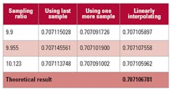
To see how this might work, an Excel spreadsheet was used to model a 3-MS/s sample rate and a 300-kHz maximum input frequency sine wave. At a 375-readings/s rate, 8,000 samples could be acquired. A few noninteger sample rate-to-signal frequency relationships close to 10:1 were tried to simulate uncorrelated sampling. In this model, the first sample was aligned with the beginning of the waveform and was not interpolated. More generally, the paper discusses treating both the first and last sample differently to account for their positions relative to the beginning and end of complete cycles. The table shows the results of the experiment.
Reference
- Mog, G. E. and Ribeiro, Dr. E. P., “Mean and RMS calculations for sampled periodic signals with non-integer number of samples per period applied to AC energy systems,“ Universidade Federal do Paraná – UFPR, Centro Politécnico da UFPR, Brazil, October 2004.


