Amplifier Extends Battery Life of Heart-Rate Monitor
This file type includes high-resolution graphics and schematics when applicable.
1. Shown is a typical smartwatch heart-rate display.
Wearable technology for personal health monitoring is the wave of the future and potentially very big business. Every day, there’s a new wrist band or smart watch capable of monitoring heartbeat, workout activity (stand, move, and exercise), calories, heart rate, sleep patterns, and more. In this article, we will look at the technology behind heart-rate monitoring (Fig. 1), its challenges, and ways to reduce power consumption, thereby extending the useful life of the wearable device between recharges.
Every Microampere Counts
A 200-mAh smartwatch battery must typically support one day of usage or two weeks of standby time between recharges, with daily usage roughly defined as four hours of active operation in a 24-hour cycle. The corresponding daily allowance for the smartwatch’s electronics (microprocessor, memory, sensors, display, and power management) is 50 mA. Accordingly, a typical operational amplifier absorbing 1.5 mA will claim a full 3% of the available current, corresponding to seven minutes of usage time. Indeed, every microampere counts.
Heart-Rate Monitoring
Sensing your heartbeat by touching your pulse is pretty easy. The blood is pumped impulsively by the heart at the rate of roughly once per second (1 Hz). A contraction of the heart muscle corresponds to a flow—a volume of blood pushed through your arteries—and a relaxation of the muscle corresponds to an ebb.
As your heart beats, arteries expand in response to the incoming blood flow and contract between heartbeats. Your pulse is thus sensed and verifies that you are alive. What is more difficult to determine, though, is your heart rate. This is where wearables, in the form of wrist bands and smartwatches, come into play.
PPG
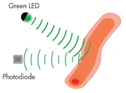
Reflective photoplethysmography (PPG) is a technique that uses light pulses to measure heart rate by sensing volume variations in the blood flow resulting from the heart’s pumping action (Fig. 2). Green light produces the largest modulation depth in flowing blood, with maximum absorption at flows and minimum at ebbs (more blood equals more absorption).
2. Reflective photoplethysmography (PPG) uses light pulses from a green LED to measure heart rate by sensing volume variations in the blood flow resulting from the heartâs pumping action.
The PPG green LED emits a short light pulse that penetrates the skin and is reflected back. The portion of the light reflected by the blood is modulated by its ebbs and flows, and detected by a photodetector as an ac signal at the frequency of the heartbeat. Static portions of the targeted area reflect light as well, detected as a dc signal that will be subsequently discarded by the signal processing.
Signal Amplification
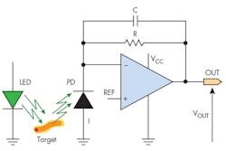
The current signal produced by the photodiode in response to light from the green LED is typically processed by the heart-rate monitor’s analog-front-end (AFE) circuit. At the core of the AFE is a low-power operational amplifier. The op-amp transimpedance configuration (Fig. 3) amplifies the photodiode (PD) current I by a factor R, yielding an output voltage VOUT = I*R. The capacitor C implements a lowpass filter of time constant RC that lets the low-frequency heart-rate signal pass, but filters out any higher-frequency noise.
3. The op-amp transimpedance configuration amplifies the photodiode (PD) current I by a factor R, yielding an output voltage VOUT = I*R.
The Ideal Amplifier for Heart Monitoring
The ideal amplifier for this application would combine high speed, low power, precision, and low-input current noise. The MAX44260, developed by Maxim Integrated, combines features to fit this need. Delivering 15-MHz bandwidth with only 750-µA supply current, the MAX44260 offers high efficiency in terms of megahertz per microamp while consuming little power (50% less than comparable devices, according to Maxim). Its 1.2-fA/√Hz current noise density helps minimize current-to-voltage conversion error.
Thanks to its shutdown pin, it’s possible to keep the device alive only when needed, which adds to the power savings. Operation down to 1.8 V also saves power, and becomes an important feature as more portable and low-power systems move to lower voltage rails.
Signal-Processing Advantages
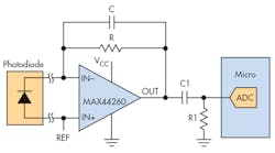
The MAX44260’s design inherently boosts immunity from RF signals present in wearable devices. Its low input bias current (0.01 pA typical at ambient temperature) becomes critical when measuring high-impedance sensors or photodiodes in which a high input bias current can compromise or distort the sensor reading. In addition, the combination of low voltage offset and low noise can be beneficial when driving either a standalone analog-to-digital converter (ADC) or one that’s integrated inside a microcontroller (Fig 4).
4. The combination of low voltage offset and low noise lends itself well to driving either a standalone analog-to-digital converter (ADC) or one thatâs integrated inside a microcontroller.
Conclusion
It’s clear how important it is to minimize power dissipation, input bias current, and input noise while maximizing bandwidth and RF immunity for the op amp in a heart-rate monitor’s AFE circuit. To that end, the MAX44260 1.8-V, 15-MHz, rail-to-rail op amp can help meet those goals for today’s wearable healthcare monitoring applications.
Nazzareno (Reno) Rossetti is a seasoned analog and power-management professional, a published author, and holds several patents in this field. He holds a doctorate in electrical engineering from Politecnico di Torino, Italy.
Steve Logan is an executive business manager for Maxim’s signal-chain product line. Steve joined Maxim in 2013 and has over 15 years of industry experience, both in business management and applications roles. Steve graduated from San Jose State University with a Bachelor of Science in electrical engineering.


