Interestingly, at the recent Applied Power Electronics Conference (APEC) 2003 in Miami, Fla., two papers in the Magnetic Devices and Materials session analyzed the impact of such advances on distributed power system (DPS) front-end dc-dc converters, and interleaved multiphase converters. While researchers from Center for Power Electronic Systems (CPES) at Virginia Polytechnic Institute and State University’s Bradley Department of Electrical and Computer Engineering investigated the influence of integrated magnetics and passives on DPS front-end converter, scientists from Polytechnic University of Madrid, Spain explored integration of inductors on the same core for interleaved multiphase converters. In their analysis, developers from Spain paid special attention to losses, size, and coupling.
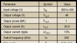
In paper 27.1, researchers from CPES presented a comparative study of the integration of passive components in an asymmetrical half-bridge circuit (AHBC) for DPS front-end dc-dc converter application, where the drive is toward 1U (= 1.75 in.) standard. The CPES paper analyzes the advantages and disadvantages of passive modules at different integration levels, from the standpoint of volume, profile, efficiency, EMI and thermal issues. According to this paper, the AHBC topology is used as a test because of its simplicity and popularity in this application. Consequently, the researchers have constructed four such AHBC converters using discrete passive components, nonplanar integrated magnetic components, planar integrated magnetic components, and passive integrated power electronic module (IEPM). Accordingly, they have been labeled as baseline, generation I, generation II, and generation III types. The experimental tests conducted on these four different converters by the CPES researchers indicate that the generation III converter incorporating passive IEPM module offers highest power density, lowest profile, lower temperature rise and similar efficiency. The specifications for the front-end dc-dc converter are as shown in the table.
The study indicates that the highest components in the older discrete based baseline converter are the magnetics, which determine the profile of the end product. By comparison, in the latest passive IEPM based generation III, the planar integrated magnetics structure cuts the profile of magnetic components substantially, making dc blocking capacitor as the highest component to influence the profile of the end product. Hence, it is integrated inside the planar magnetic structure, along with all other high frequency passive components (Fig.1) to achieve the desired profile in the end product. The result is highest power density without changing the electrical, thermal and EMI performance much, the paper concluded.
With the thrust toward multiphase solutions for powering new generation of microprocessors, the phase count rises as current requirements soar with dropping processor voltages. And so does the number of inductors needed, thereby increasing losses and the component count. This is turn is forcing developers of interleaved multiphase converters toward integration of inductors on the same magnetic core. In paper 27.2, researchers from the Polytechnic University of Madrid provide analysis of such integration, as well as some guidelines in constructing such integrated structures. In essence, the researchers have analyzed four such configurations (Fig.2). They are as follows:
- Decoupled integrated inductors with inverse coupling.
- Decoupled integrated inductors with alternate coupling.
- Coupled inductors with alternate coupling.
- Coupled inductors with inverse coupling.
Simple electrical models have been obtained for these structures and analyzed. As per the findings of the paper, configuration #4, coupled inductors with inverse coupling, seems like a better alternative for magnetic integration. Besides reducing the size, this method also reduces rms value of the currents. And, depending on the magnetizing inductance, the AC flux in the core is lower. The paper suggests that very high mu materials are suitable for this application. Also, in this application, the filtering of the harmonics is accomplished with a single inductor of very low inductance value.
