This file type includes high resolution graphics and schematics.
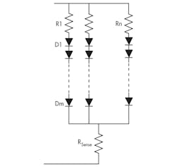
LED-based lighting is replacing incandescent and gas-discharge lamps in many situations. As practical lighting sources, and considering their directional nature, LED fixtures usually use multiple LEDs arranged in an array, with “m” LEDs in a serial string and “n” such strings in parallel (Fig. 1).
For the array configuration and the exponential I-V characteristics model of a single LED,1 it’s also possible to have a similar model representing the loading of such an array.
Related Articles
- Master The Fundamentals Of LED Illumination
- Generate Realistic Models For LED Current Versus Voltage
- Use Flyback Converters To Drive Your LEDs
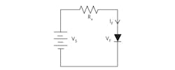
Since the single LED is a diode with a nonlinear forward-voltage/current, driving it with a fixed voltage source is generally not recommended. Rather, a serial (current-limiting) resistor is needed to equalize the power source and the load,(Fig. 2).
However, sizing this resistor requires a significant analytical manipulation. Using the single-LED exponential model, a Kirchoff’s voltage law (KVL) equation around the circuit loop gives:
which can be rearranged to:
where a, b, and c are model parameters for a selected LED, as defined in the reference.
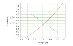
This is a challenge to solve symbolically, but it can be solved numerically with mathematical software tools. Alternatively, it can be solved graphically by separating the two key I-V relationship equations, v+ RxIF = Vs and IF = aebv + c.
For example, using a Lumileds Luxeon Rebel ES LED with a 3.2-V dc source and a desired drive current of 0.5 A, the horizontal current line intercepts the LED curve at 2.92 V (Fig. 3). Therefore, the series resistor will be Rx = (3.2 – 2.92)/0.5 = 0.56 Ω.
However, the graphical approach would not handle an LED array effectively, and the numerical method works better. To represent the array current iA, the exponential model for the (m × n) array is modified, since voltage drops across current-limiting resistor Rn and sense-resistor RSense are usually small compared with driving-source Vs:
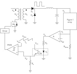
With the array model, the switch-mode buck-regulating current driver in a closed-loop configuration (Fig. 4) can be described by a set of equations starting at the feedback point, circling around the control loop, and ending at the driver output:
• Current sensing:
Vf = iA • RSense (4)
• Error amplifier:
Ver = A(VRef – Vf) (5)
• Effective error:
VRamp(D • Ts) = Vef (8)
• Power stage:
Reference
1.“Generate Realistic Models for LED Current Versus Voltage” Keng C. Wu; Electronic Design, Vol. 61, No. 1, p. 52, Jan. 10, 2013, http://electronicdesign.com/power/generate-realistic-models-led-current-versus-voltage
This file type includes high resolution graphics and schematics.
About the Author
Keng Wu
Keng C. Wu, a power electronics consultant, has published five books on power processing, was awarded “Author of the Year” twice (2003 and 2006 Lockheed Martin), and presented a 3-hour educational seminar IEEE APEC-2007 S17. He has held more than a dozen U.S. patents. He earned a BS from Chiaotung University, Taiwan, and an MS from Northwestern University, Evanston, Ill.


