The ability to turn on loads in a controlled manner is important in applications where the power budget is limited. Hard switching a load can cause the input power rail to droop and result in a fault. In some applications, a short of a single rail can damage the entire system by resulting in the reset or damage of the main supply or excessive power dissipation on the system board.
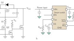
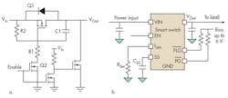
This is why system designers often include high-side load switches as part of the power-supply architecture (Fig. 1). To achieve some of the desirable functions such as low-voltage enable/disable, load discharge, and slew-rate control, quite a few discrete components need to be used.
Typical high-side load switch circuitry fails to account for the results of a droop in the power rail when the load is suddenly applied. Smart switches, which are available from several semiconductor manufacturers, provide multiple levels of protection.
Related Articles
- Additions Boost Fault-Protected Current Limited Precision At Higher Supply Voltages
- Regulator Limits Dissipation While Capping Current At The Desired Level
- Current Overdrive Detector Circuit Protects Automotive ECUs
For example, Vishay offers a smart switch that provides programmable soft start, programmable current limits, over-temperature protection, a fault flag, and under-voltage lockout. It will turn off and retry to turn on through the full soft-start procedure 150 ms after the switch is off and the fault is removed. Other versions will turn off the switch under fault conditions and remain off.
Despite that sophistication, a smart switch device designed specifically for load switching and fault protection applications is much simpler and has far fewer components than a load switch comprising discrete components. Besides the obvious benefit of reduced board area, additional benefits include:
• The response of the smart switch is very accurate and repeatable due to on-chip current-sensing and current-limiting circuitry.
• The smart switch really adds value in terms of functionality compared to a discrete solution. The feature set can include over-current protection (OC), over-voltage protection, adjustable and fixed slew rate, output discharge, and reverse blocking.
• Flat on resistance is achieved over a wide operational input voltage. By using a charge pump, a constant voltage can be applied to the MOSFET gate regardless of input voltage to ensure consistent on resistance. This is virtually impossible to achieve discretely.
This file type includes high resolution graphics and schematics when applicable.
Application Areas: Power-Supply/Battery Power Savings And Protection
The high-side load switch often is used in applications in which battery life is very important. In such systems, all but the most crucial of circuitry is removed from the battery output. A number of high-side load switches can be used to disconnect unused loads and save power.
Besides the battery life improvement, the advantage of using a current limiting switch instead of a resettable fuse is clear from the following comparison. A resettable fuse is commonly used in notebook applications, such as in backlighting circuits where a boost regulator is used to power strings of LEDs. If a short occurs on the output, it can compromise the system rail because a non-synchronous boost has a path from the input to the output via the inductor and diode (Fig. 2).
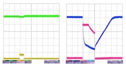
A comparison of the input current and voltage of a 12-V bus when protected by a polymeric positive temperature coefficient device (PPTC or polyfuse) shows that the smart switch reacts faster to the short and starts limiting current quickly, resulting in only a minor droop of the input supply, compared to the wild voltage and current swings on the resettable-fuse configuration. Using the smart switch means that less bulk capacitance can be used on the input to the system and that there is no risk of the system being reset due to a mains-supply fault.
More Applications: Solenoid Driver
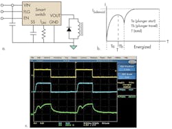
An interesting use for a smart switch is as a solenoid driver. A solenoid is essentially a large inductance. When voltage is applied, the current through the solenoid will rise at a rate determined by its inductance and dc resistance. When enough magnetizing current is applied to the solenoid, it will activate, causing a dip in current before the current again reaches steady state. At this point the input signal can be changed to pulse-with modulation (PWM), using a micro controller with a predetermined control program, to lower the operating loss or simply to reduce the power applied to the solenoid.
In this particular instance of the application, in which an SiP32429 is being used to drive a solenoid, the device has a turn-on delay time of 550 μs, a rise time of approximately 7 ms into a 10-Ω load, and a turn-off delay time of 1 μs. This gives a total of 7.56-ms minimum operation time. This is more than adequate for operation of solenoids up to 20 Hz for smaller 5 VA.
On the scope screen capture of Figure 3, yellow is the applied voltage, blue is the solenoid voltage, and green is the solenoid current. In the schematic, the solenoid is connected between 0 V and VOut of the device with a Schottky in parallel to disable transients and for energy removal. This approach also can be used as a relay driver in the same configuration.
An advantage of using a current limiting, slew-rate controlled load switch in this application is that the protection features will never allow a constant on condition of the solenoid. If the smart switch encounters an over-current event, it will shut down before an automatic retry is attempted. If the failure persists, the part will again shut down.
Brushed DC Motor Driver Or Fan Driver Applications
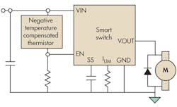
The SiP32429 works as a high-side switch in motor driver applications (Fig. 4). The schematic for this is quite straightforward. The fan is connected in parallel to a Schottky diode (for switch-off freewheeling) between VOut of the SiP32429 and ground. The enable pin is connected between VIn and ground via a thermistor/resistor divider.
This approach can be used, for example, in applications in which a single-speed fan is used for cooling. When a system over-temperature is sensed, the extra functionality of the smart switch is quite useful. If the device were to overheat because of extreme ambient temperature, the flag pin would be used as an alert to shut down the main system.
Another positive aspect of using such a part is in the current limiting features. If the fan were to become blocked, then the SiP32429 would react within 1 µs to remove the voltage, preventing massive voltage spikes created by the fan inductance.
Power-Supply Enabling And Sequencing
Another alternative application is a smart switch supplying voltage to a step-up/step-down switching regulator or, indeed, several of these circuits (Fig. 5). The ability to slowly charge into capacitance allows again for smaller source power-supply dimensioning while the power-up sequencing will be easily achievable. The possibility of removing several circuits when the system is in standby reducing quiescent current is another application specific option, which is very useful.
Conclusion
Broadly, protecting the system power rails from fault conditions is an important part of a good power design. A high-side load switch with features such as current limiting and slew-rate control is very useful in implementing protection schemes or simple circuits where inductive and capacitive loads require soft switching.
In applications where the source has a large amount of energy, a short can cause considerable damage if the power architecture is not designed for fault tolerance. In such applications, the use of a current limiting switch is not only prudent, it also can reduce system cost and improve reliability. Even if a fault does occur, the damage is limited and can be serviced at a lower cost.
Owain Bryant is a field application engineer with the IC Division at Vishay Intertechnology. Previously, he was the senior electronic engineer at Dyson, Classe Audio, and Harman Becker Automotive Systems. He holds a BEng (Hons) from Cardiff University.
