While switch-mode power supplies operate at frequencies well above the range of human hearing, they can produce audible noise under certain load conditions. Potential sources of audible noise can vary widely. Noise can be the result of design flaws such as an oscillating output voltage, or it can be generated by noisy components such as capacitors or transformers. In some cases, the high-pitched whine or hissing noise you hear can be something as simple as a cooling fan oscillating at an unusual frequency or the supply’s proximity to an external electromagnetic interference (EMI) source such as a fluorescent light or another converter causing a beat frequency due to the interaction of the two. With today’s need for reduced standby power, converters often employ lower average switching frequency modes, which also tend to increase audible noise.
Related Articles
- Use A Flyback Topology To Drive Custom LED Lighting
- Use Flyback Converters To Drive Your LEDs
- Mind The Gap And Improve Your Low-Power Flyback Transformer Design
Here is an approach to troubleshooting the most common sources of audible noise in flyback power supplies, along with potential solutions to the problem. All of these procedures can be conducted with an electronic load and a programmable ac source or Variac. Keep in mind that in some cases the audible noise your supply is generating may be so low that it will not present an issue if the power supply is intended for use in a sealed enclosure.
Likely Suspects
The most common source of audible noise in a flyback supply is a noisy component. Typically, ceramic capacitors or ferrite transformer cores generate this noise. Noise in a ceramic capacitor is usually a product of the reverse piezoelectric effect. When a voltage is applied across a dielectric structure, it can induce a mechanical stress or strain that causes the material to deform. As the material deforms, it displaces the air around it and generates noise.
Since the reverse piezoelectric effect occurs during large voltage swings, designers can focus their search on those ceramic capacitors that experience high dV/dt swings. In a typical power supply, they include snubber and clamp capacitors as well as ceramic output capacitors. Don’t overlook auxiliary or bias outputs where low output currents allow ceramic output capacitors to be used.
To quickly identify if a ceramic capacitor is generating noise, replace it with a metal-film-type capacitor with the same value and appropriate voltage rating. If the noise level declines, you have located a noise source in your circuit.
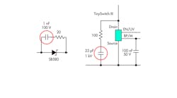
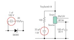
The source of noise may be a clamp capacitor. Try replacing it permanently with a metal-film-type capacitor or a ceramic capacitor using a different dielectric material (Fig. 1). Another option is to change the type of clamp you are using to, for example, a Zener clamp circuit. If the noise problem lies in a snubber capacitor, consider replacing it with a metal-film type or increasing the value of the resistor in series to reduce dV/dt seen across the capacitor. You can also try to switch to a ceramic capacitor with a different dielectric and see if the noise level goes down.
When the noise problem resides in a ceramic output capacitor, try substituting an electrolytic capacitor or changing to a capacitor with a different dielectric. Alternately, try replacing the problem capacitor with multiple ceramic capacitors in parallel. The smaller size of each capacitor reduces surface area and, in the process, changes the mechanical resonance of the capacitors.
Transformer-Core Noise
Noise generated by transformer cores, on the other hand, typically is caused by magnetostriction, a process similar to the reverse-piezoelectric effect. That is, many ferromagnetic materials change shape when they’re subjected to a magnetic field. As the magnetic field changes the transformer core, it can cause the core to physically vibrate. When this vibration reaches the mechanical resonance frequency of either the transformer core or bobbin, it will be amplified and may become audible. In ac-electrical devices with line frequency transformers that experience 50/60-Hz applied magnetic fields, the maximum length-change happens twice per cycle, producing the familiar 100/120-Hz hum.
For switching power supplies, the fundamental frequency is above the audible range. However, it is often modulated at light load to reduce the average frequency and reduce losses. This modulation includes lower-frequency harmonics that similarly create audible noise in the magnetic components.
If a new design is experiencing this problem, begin the debug process by ensuring it is not being stressed by an improper design implementation. First, verify that the input voltage and output load the transformer sees match design specifications. If the power supply is run below the specified minimum input voltage or above the specified output load, regulation may be lost for part of the ac cycle. That, in turn, can cause increased flux level swings in the core and generate noise.
If input voltage and loading are within specifications, the next step is to verify that the input bulk capacitor value is accurate. An input capacitor that is too small for the application will cause dc-bus voltage to droop too low between ac-refresh cycles, causing a loss of regulation for part of the incoming ac cycle. This will modulate the flux in the magnetic components at twice the line frequency and create the potential for noise.
The variety of moveable elements in a transformer includes windings, isolation tape, and bobbins. Each can be a source of audible noise. Current in the coils can produce electromagnetic fields that can generate forces that lead to mechanical vibration in the transformer’s various components.
The most effective way to minimize the physical movement of transformer elements is to use an adhesive material or varnish. Dip-varnishing the core, for example, is widely used to prevent the core from vibrating against the bobbin. While vendors offer a variety of varnishing techniques, we recommend using dip rather than vacuum impregnation because vacuum impregnation significantly increases winding capacitance, reduces efficiency, and drives up EMI.
If a design calls for a long-core-type transformer, another strategy is to use a standard core length instead. Long-core variant transformers such as EEL- and EERL have much lower mechanical resonant frequencies than long cores. These lower resonant frequencies tend to increase audible noise. Moving to a standard core length with its higher resonant frequencies can mitigate the problem. It is important to note, however, that switching to a shorter standard core may make it necessary to move to a larger core size to supply sufficient winding-window area.
Pulse Bunching
Pulse bunching is another potential source of audible noise. It occurs when conducted current pulses in a design collect together, followed by an extended number of skipped pulses. This grouping of pulses introduces components into the switching frequency patterns that are often in the audible range. Pulse bunching tends to occur most frequently in power supplies that use on/off or a similar type of control.
To determine whether a design is experiencing these phenomena, break the MOSFET drain trace and insert a current loop to monitor the drain current switching pattern. Using a current probe and oscilloscope, capture a set of drain switching pulses on a wide time scale with the supply operating at normal load. Figure 2 compares waveforms showing pulse bunching with normal switching patterns. If the scope displays pulses like the one depicted on the left where a number of pulses in a row are followed by two or more skipped pulses, the design is probably experiencing this problem.
Typically, pulse bunching indicates that the feedback circuit is so slow it is introducing a lag into the controller’s response. Debug this problem by first verifying that all of the component values in the feedback circuit match those specified in the design.
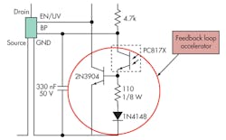
One possible solution is to switch to a D-type optocoupler. D-type devices offer a much higher gain than standard optocouplers. Another strategy would be to add a feedback-loop accelerator circuit to improve response time. This circuit will ensure that the optocoupler transistor always operates in the active region, preventing it from saturating and giving it a faster response (Fig. 3).
Conclusion
While audible noise in a flyback supply can come from a variety of sources, the most common culprits are ceramic capacitors or ferrite transformer cores. If your supply is generating loud audible noise when tested, try these strategies. In most cases you can quickly identify the faulty component and resolve your noise problem.
Peter Vaughan is the applications engineering director at Power Integrations. He has been with the company in a variety of senior technology and applications roles since 1996. He can be reached at [email protected].


