After accounting for the time required to run a full equipment cycle for each mode at each receiver bandwidth and antenna position and calculating that it would take 13.46 years to perform all the testing for the data set they wanted, the company changed its requirements. When the testing was finally completed, it had taken about four days to do the job, but there never were any in-the-field failures.
A test effort primarily is a function of the amount of risk that the manufacturer or customer is willing to accept. If the EUT is a $20 hand-held game with a digital display, it is not likely to receive the same level of scrutiny as a $600,000,000 interplanetary spacecraft—especially in the area of susceptibility. In any case, test planning is important, and if prayer is an element of the plan, then the plan is flawed.
Creating a sound EMC testing program isn’t that difficult. But it would help if the planning organization had an EMC-knowledgeable engineer to do the work and act as the mentor for the other designers. Essentially, five steps are involved in performing an EMC test regardless of whether it is for design/development or for formal acceptance:
1. Establish test objectives.
2. Do a pretest requirements analysis.
3. Perform the testing.
4. Evaluate the results.
5. Correct any problems.
For this article, each step of the test plan is considered independently, but keep in mind that all five steps are interlinked.
1. Establish Test Objectives
The objective of all EMC tests is to verify that the EUT meets its functional requirements in an adverse EM environment. Test objectives are uniquely determined by the equipment design. The EUT has to do what it’s supposed to do. If it doesn’t, then no one will care if it meets the EMC requirements.
To perform all functions properly, the EUT must be self-compatible. Sometimes this is described under the heading of signal integrity, depending on whether it is an EMC or a digital designer discussing the issue.
Self-compatibility should already have been established by design/development testing long before any formal EMC testing is done. The EMC test environment, which drives the tests that are required as well as the frequencies over which they are performed, is determined either by site RF environmental information or by requiring the EUT to meet specific standards. EMC compliance is a legal issue, not some equipment feature that would be nice to have. EMC test and evaluation determine if the objectives were met.
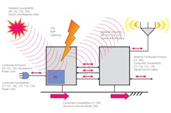
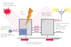
To prove the objectives have been met, it is necessary to devise tests that verify that the equipment does not affect the EM environment and that the environment does not affect the operation of the equipment. That’s the reason for performing both emissions and susceptibility tests. These tests are illustrated in Figure 1.
Figure 1. Equipment Requirements
Overview of Military, EU, and FCC Requirements
EMC is inherent in the design. It is not a characteristic that can be added after everything else is completed. Consequently, EMC testing and test planning should begin simultaneously with the start of the system’s design and be tracked so that designers can quickly receive feedback on the EMC characteristic of the design.
EMC design is not some last-minute effort that takes place after the first thousand have been produced. An EMC problem discovered at the last minute may result in scraping the design and starting over with subsequent lost time to market along with any nonrecurring engineering costs.
Even though the EMC characteristics of the system may have a big impact on the customer’s assessment of product quality, EMC is not a quality-control function. That doesn’t mean that both quality assurance and control shouldn’t be involved in assuring that the product continues to meet its EMC requirements. However, if nothing has happened during design to establish EMC from the beginning, it won’t be there by the time quality control gets involved. By law, EMC requirements must be met before the item can be sold, and meeting them does result in a more reliable product.
It’s time to quit thinking of EMC as a cost and start thinking of it as a benefit. This is especially true with robotics and controllers because of EMC functional safety requirements.
Depending on how the equipment is used, susceptibility requirements can result in system safety issues forcing both a hazard analysis and a risk assessment (HARA). A good reference is the IET 2008 Guide on EMC for Functional Safety published by the Institution of Engineering and Technology (www.theiet.org).
At this time, the FCC places limits only on the emissions that can be produced by the EUT. It doesn’t care whether it’s an RF health hazard or whether the EUT will operate properly when the customer buys it or even if it interferes with the customer’s own equipment—only that its conducted and radiated emissions do not interfere with the neighbor’s enjoyment of the public broadcast network.
The EU requirements address this same concern but place additional controls on the conducted and radiated susceptibility of the device. This is the primary reason that the EU EMC requirements have become the de facto world standard for commercial equipment.
Military requirements focus on nearly the same problems as the EU. But because military requirements are platform or mission oriented and their EM environment is more severe, so are the emissions and susceptibility requirements. MIL-STD-461 provided the foundation for most of the present EMC test requirements for susceptibility.
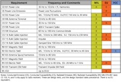
Table 1 compares the EMC tests called out in MIL-STD-461E/F with the EU and FCC requirements and is keyed to Figure 1. Since most EMC test procedures have common evolutionary roots, those in the different standards are very similar.
Table 1: Emissions and Susceptibility Tests
To establish the test objectives, it’s necessary to consider:
• What specification the EUT is required to meet.
• What the system is supposed to do.
• Which of these functions are the most important.
• What risks are there if the system does not pass.
• What is the best way to prove that it functions properly.
2. Do a Pretest Requirements Analysis
It’s difficult to perform EMC tests without an EUT, but that doesn’t mean that the equipment design has to be finished for testing to occur. The approach, however, will depend on the extent of the EUT design completion. If the end item is a replaceable electronic module (REM) for a USN aircraft, there may be a lot of additional ancillary hardware required to enable a meaningful test. On the other hand, if the item is a stand-alone system or subsystem, no additional hardware may be required.
In any case, as soon as some functional circuits in hardware form become available, testing should start. It’s amazing what problems can be uncovered by design/development testing, and the sooner it can be done the better.
While waiting on hardware to be built, there are several informational items that need to be collected from the designers and the original proposal documentations or by analysis:
• The functional operating modes and the circuits that are active in the various modes. EMC test requirements specify that the worst-case emissions and the worst-case susceptibility must be determined and evaluated.
• Critical I/O interface circuits and what is needed to simulate or load them or, if ancillary equipment is required, to make arrangements to obtain the equipment in time for testing.
• Listing of oscillator, data generator, clock frequencies, and their operating voltage/current levels as a guide to determining potential sources of emissions.
• Listing of any analog circuits, including operational amplifiers, sensors, A/D converters, and mixers, and their operating parameters as a guide to determining potentially susceptible circuits. For each of these, it also is necessary to determine what characteristic is important and how to measure it.
Next, begin establishing what tests can be performed at different points in the design process. As the design nears completion, test results are more meaningful than those early in the design/development stage, but it is not necessary or advisable to wait until the EUT is complete before collecting EMC progress data. It is perfectly acceptable to make measurements on a dead-bug wired prototype sitting on a designer’s workbench and powered by lab power supplies.
Radiated and conducted emissions tests will provide frequency and relative amplitude data plus indicate how much suppression is likely to be required. If the emissions levels are off the top of the display, it may suggest that a different design approach should be considered.
The same thing is true with susceptibility tests. Based on the suppression that may be required to meet the emissions requirements, reduce the susceptibility test levels by that amount and see if the EUT will work in that environment.
Most of the time EMC susceptibility tests do not result in catastrophic failure so malfunctions generally only occur during testing. This means that a system cannot be evaluated by doing an operational test then subjecting the EUT to the EMC environment and repeating the operational test. Monitoring must be done in real time while the EUT is subjected to the EMC environment.
It often is a major challenge to figure out how to prove that the system is performing properly in real time during EMC susceptibility tests. It’s also necessary to determine what data is required to determine acceptability of the EUT at the time of measurement. For example, if the test is being run on a breadboard on the bench, it will have a decidedly different RF profile than it will have after production PCBs are available and it’s properly packaged. Loop areas will be smaller, circuits should have lower crosstalk, and the PCB and the packaging may provide additional decoupling and some shielding.
If the system has built-in test equipment or test circuits, these often can be used to determine susceptibility. In all cases, try to avoid connecting any hard-wired devices to the EUT. Just these additional wires acting as antennas will increase the RF energy pickup by the EUT and result in greater susceptibility.
In addition, whatever is being used for monitoring will radiate RF energy that will appear as if it is coming from the EUT and conduct RF energy into or from the EUT. This is a major problem if tests are being performed at an open area test site.
Once the energy is in the EUT or on its interconnecting cables, there is no way to determine where it came from. Monitoring test points without contributing to the emissions or susceptibility of the EUT often needs a great deal of creativity. For example, to measure acoustic noise in headsets or energize microphone circuits may require the construction of specialized acoustic couplers. To eliminate extra multiconductor cables, the use of multiplexers with electro-optical converters and fiber-optic interfaces might be necessary.
Sometimes telemetry equipment or other remote reading devices such as closed circuit TV with telephoto lenses to measure voltages, watch displays, or read meters must be used. If buttons need to be pushed, then pneumatic plungers with controllers may have to be built. Depending on the frequency, solenoids may produce much RF noise.
Some monitoring is really interesting. For example, to measure a cell phone’s RF specific absorption rate, such as its heating effect, requires an artificial head filled with an electrolyte and thermal sensors, not just a blob of hamburger and a thermometer.
If the EUT is a completely assembled, stand-alone system, then the pretest analysis and the testing should be relatively easy to do. If the system is a REM or a subsystem that can only work while part of a larger system, then the rest of the system must either be used in conjunction with the test sample or the remaining parts of the system must be simulated.
Any ancillary equipment or overall system parts that are tested along with the EUT must have EMC characteristics that are better than or equal to those of the EUT. Otherwise, the EUT gets penalized with the emissions and susceptibility of the additional equipment. This may necessitate special testing just for the additional equipment.
It’s not good enough to simply acknowledge that the overall system met the requirements, especially with MIL-STD-461, because tailoring may have allowed the system to exceed the specification limits in various frequency ranges where the EUT must meet them. Without examining the test report and doing a detailed raw data analysis, the tailoring levels probably would not be known. The result summary would only indicate that the EUT met the requirements.
The more complex the system, the more likely that special software will have to be written to exercise the EUT and the associated EMC ancillary equipment. There are two primary functions for the software. During emissions testing, the software must continuously exercise all potentially worst-case emitters. During susceptibility testing, the software must continuously exercise all worst-case susceptible circuits.
If the software is not capable of exercising all circuits simultaneously, this will result in additional software-induced modes of operation. The various EMC tests then must be repeated until all circuits have been exercised unless an analysis can prove that the circuits that were operational during the tests are worst case.
Because both emissions and susceptibility levels are directly affected by loop area and loop resonance, the physical layout of the circuits on the PCB has to be examined, measured, and considered in the analysis. The analysis can’t be done by simply looking at the schematic and entering voltages and currents into PSPICE.
During susceptibility testing, the test operators must be able to determine in real time that a malfunction or degradation of the EUT has occurred. It would be advantageous if the test software could do this. If the EMC measurement equipment is available in-house, the software could be written to control EUT and EMC test equipment as well as data reduction and analysis.
In addition to determining which tests are required, the pretest requirements analysis should include:
• The equipment to do these tests.
• The test and facilities requirements.
• Whether tests can be done in-house or must be done at an outside testing laboratory.
Part 2
Part 2 will address how to perform design development tests, including the kinds of information that should be supplied to an outside test agency if that is the route taken; how to evaluate the test results; and what to do if the EUT fails. It will appear in EE’s June issue.
About the Author
Ron Brewer is a senior EMC/RF engineering analyst with Analex at the NASA Kennedy Space Center. He can be reached at [email protected]
May 2010


