Achieving Full Compliance on the First Try
Numerous obstacles can prevent a company from meeting the market window for a new product. For those that create electrical and electronic products, one of the major obstacles can be EMC. EMC compliance is closely regulated in most countries, and all products must achieve full compliance for every country in which they will be sold.
Because a final product must be evaluated, testing usually is performed at the end of the development process. If the product fails, time is lost while the designers find and fix the problems and then restart the process of compliance testing.
Many companies have improved their chances of succeeding on the first try by adding precompliance EMI testing to their development process. The most successful approach is to perform these checks at multiple stages: breadboard, lab prototype, production prototype, and pilot run. Although these measurements are not conclusive, positive results are a good indicator that a new product is likely to pass full compliance testing.
Precompliance testing and compliance testing address radiated and conducted emissions. Radiated emissions are high-frequency signals that the EUT emanates into the surrounding air. Conducted emissions place unwanted signals on the AC power line connected to the EUT. Both types of emissions have become more prevalent as digital clock speeds moved into the gigahertz range.
The Regulatory Environment
The applicable agencies and regulations vary by region or country. For example, products sold in Europe must satisfy the European Norms (ENs), which are based on recommendations from the Comité International Spécial des Perturbations Radioélectriques. CISPR, which translates as the special international committee on radio interference, was founded in 1934 and is part of the International Electrotechnical Commission (IEC).
Regulatory agencies in many nations use CISPR as a guide when enacting local requirements. Other countries have locally developed standards; Australia, China, Japan, and Taiwan are prime examples. A few others, including Mexico, are creating standards for indigenous and imported electrical and electronic products.
CISPR 16-1-1 is the recommendation covering measurement receivers used in EMC compliance testing. Recently, this recommendation was revised to include the use of commercial signal analyzers for some EN tests. A suitable analyzer must include specific types of signal detectors, provide the necessary measurement bandwidths, and be capable of measuring low-level signals, a function of input sensitivity.
Compliance vs. Precompliance
Full compliance testing typically is performed at an accredited test lab staffed by trained practitioners. These facilities must have a qualified open-area test site or semi-anechoic chamber, an antenna tower, a turntable, and a CISPR 16-1-1-compliant receiver. The cost of establishing such a facility can be quite high, and the resulting cost of compliance testing is many times that of precompliance.

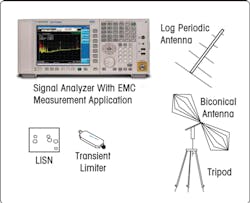
Figure 1. Precompliance Measurement System
When a company’s development engineers perform precompliance testing, they are making preliminary assessments in accordance with the relevant standards. Even though these measurements only give an approximation of expected EMI performance, they still provide useful reassurance regarding the chances of passing compliance testing.
Precompliance Measurements
Figure 1 shows the equipment typically used in precompliance measurements. The receiver is an RF/microwave signal analyzer with a built-in EMC measurement application. The major accessories are a line impedance stabilization network (LISN), a transient limiter, and two types of antennas.
For product developers, signal analyzers that measure into the RF and microwave ranges are useful tools, especially when equipped with built-in measurement applications that simplify precompliance EMI testing. Although precompliance measurements are not complex, a few essential questions must be answered prior to testing:
- Where will the product be sold?
- What is its classification? There are four main categories: information technology equipment (ITE); industrial, scientific or medical equipment (ISM); automotive or communications; and generic or products not in other classes.
- Where will it be used? Typical categories are heavy industry, light industry, commercial businesses, and homes.
The answers point to the relevant standards. For example, an ITE device to be sold in the United States must meet FCC 15 standards. Table 1 shows the relevant CISPR, EN, and FCC standards (details are available online at www.iec.ch and www.fcc.gov).
Table 1. CISPR, EN, and FCC Designations for Similar Types of Products
Once the appropriate regulations are known, the next step is to set up the equipment and check for radiated and conducted emissions. Radiated measurements are more challenging because an antenna is used to detect the signals. Conducted measurements are easier to set up because they use hardwired connections between the EUT and the signal analyzer.
Hints for Testing Radiated Emissions
Tests for radiated emissions identify and measure high-frequency signals produced by the EUT. Every measurement must be repeated for each face of the EUT, and this is aided by placing the device on a turntable.
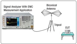
Figure 2. Basic Test Configuration for Radiated Emissions
The basic test configuration is shown in Figure 2. These tests are somewhat more complex than conducted measurements due to the ambient environment, which often includes stray signals that may interfere with emissions measurements. This can be especially problematic in metropolitan areas where ambient signals such as cellular, Wi-Fi, and broadcast are strong enough to mask EUT emissions.
Testing is faster and simpler when performed in a semi-anechoic chamber. The chamber will attenuate unwanted external signals and limit ambient signals to those coming from the equipment in the chamber.
If a chamber is not available, then a few simple techniques can help pinpoint ambient signals. For example, the simplest method is to shut off the EUT and then look for signals that remain on the signal analyzer’s display.
Another approach is to use a turntable, which allows rotation of the EUT while observing the problematic signals. As the EUT revolves, amplitude should change for EUT-generated signals and remain constant for ambient signals.
A slightly more sophisticated technique uses two antennas. One is placed at a distance specified by the test standard, and the other is located at twice that distance from the EUT. Both antennas then are attached to the inputs of an RF/microwave switch, and the switch output is sent to the signal analyzer input. Switching between the antennas will highlight the ambient and EUT signals. Those with relatively constant amplitude are likely to be ambient while those that are 6 dB lower at the second antenna are probably EUT-generated.
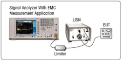
Figure 3. Basic Test Configuration for Conducted Emissions
Hints for Testing Conducted Emissions
These tests identify EUT-produced signals conducted onto the connected AC power line. Measurements are made through hardwired connections from the EUT to a limiter and the signal analyzer (Figure 3).
A few hints can help ensure meaningful results. For example, the power cord between the LISN and the EUT should be kept as short as possible because long cords act like antennas, potentially introducing ambient signals into the measurements. A somewhat contradictory tip also is helpful: Attaching a ferrite filter to the power cord is not advised because it may suppress common-mode signals from the EUT. This can produce potentially misleading measurement levels that are lower than actual.
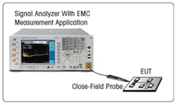
Figure 4. Signal Analyzer With a Close-Field Probe
Hints for Diagnosing Problems
The conducted and radiated tests should provide enough information to determine if the product is ready for full compliance testing or if it must return to the development team for diagnosis and design changes. When diagnosis is needed, the following process can be useful:
The essential tools are a signal analyzer and a close-field probe (Figure 4). The saved test results will be used to identify the problem frequencies. With the signal analyzer set to its spectrum-analysis mode, the probe is used to scan the EUT and locate possible sources of problem signals. At locations that produce signals with the largest magnitude, the measurement trace should be saved to the analyzer’s internal memory.
In most cases, significant reductions of unwanted emissions will require component changes, a circuit redesign, or the addition of shielding. When the revisions have been made, the EUT should be measured again using the same settings. Saved traces can be recalled and compared to the new results. Improvements in close-field results will yield similarly improved far-field measurements.
Conclusion
Successful precompliance testing indicates a greater likelihood of first-try success during full compliance testing. When performing precompliance testing, designers will benefit by using signal analyzers that offer built-in applications designed for EMI testing. Ultimately, this approach will enable product developers to quickly perform informative measurements and then return to their main task: completing the new product. For the company, this can improve the chances of meeting a window of opportunity in the marketplace.
About the Author
Dennis Handlon’s career includes experience with microwave and RF signal measurements. After receiving a B.S.E.E. from San Jose State University in 1968, he joined Hewlett-Packard as a manufacturing engineer for spectrum analyzers and, in 1985, moved to product marketing. Mr. Handlon currently is consulting with Agilent Technologies on EMI-related projects. [email protected]
Agilent Technologies, 5301 Stevens Creek Blvd., Santa Clara, CA 95051
About the Author
Comment About the Article
To join the conversation, and become an exclusive member of Electronic Design, create an account today!

Leaders relevant to this article: