An accurate timing source is the foundation for reliable operation in many communications, embedded, and industrial applications, whether it ensures synchronized communications or maintains the correct time. Because of their ease of use and low cost, quartz-based crystals are used as the timing source in many applications. However, crystals are susceptible to frequency drift, causing clocks to lose accuracy over time.
Related Articles
- Fundamentals Of Crystal Oscillator Design
- pMEMS Oscillators Make Waves Without The Crystal
- MEMS Oscillators Replace Quartz Crystal Oscillators
To clarify, drift and jitter are two different sources of error for a timing device. Jitter refers to variation in the output signal or its precision. A timing source with low jitter will output a relatively consistent frequency. Drift, in contrast, describes the change in accuracy of a given frequency over environmental changes such as temperature, humidity, or pressure, or simply over long periods of time. It is measured in parts per million (ppm).
For example, given a low-jitter, 32-kHz crystal, the formula describing the fractional change of frequency with temperature is:
where:
f0 = frequency at turnover temperature
T0 = turnover temperature, normally 25°C
k = 0.035
So from –40°C to 85°C, the frequency change could easily be –100 ppm. If maintained at these extreme temperatures, the clock may lose around 4.5 minutes per month.
This file type includes high resolution graphics and schematics when applicable.
Understanding Drift
One of the challenges of designing around drift is that issues may not arise until devices have been in the field for years. After a year, the shift in frequency associated with 4 ppm may not trouble a system. But after five years, that drift could become a frequency error that has a real effect on system performance and reliability.
Drift can affect systems in different ways. For communications systems, the impact can be significant. Consider a wireless device like a cell phone, tablet, or embedded sensor. As the frequency drifts over time, the device will begin to both experience and cause RF interference problems as it drifts into other frequency bands. It may experience synchronization issues with other devices, reducing performance and reliability. It may fail to meet the appropriate compliance standards. It could even shift into a frequency band that is illegal for it to broadcast into, causing compliance issues that could potentially be expensive to resolve. For these kinds of applications, minimizing drift to keep the frequency relatively constant is critical, potentially requiring a timing source that’s less than 1 ppm.
Similar issues can arise with system buses clocked to a drifting timing source. As the bus frequency drifts, synchronization errors could occur, resulting in lost data and unreliable system operation over the long term.
For applications that require accurate time of day or date information, drift has varying effects depending upon how the information is used. If the time is being displayed, its accuracy may become noticeable after the first few seconds or minutes are lost or gained. If the time is used for logging, such as for a medical device or embedded sensor node, the impact of drift depends on how accurate the log needs to be.
One alternative to maintaining more accurate time is to have the user manually reset the system clock on occasion. Another option for devices that have a network connection is online clock calibration. Whether these options are feasible depends upon the application.
Environmental Factors
Environmental factors vary greatly from one application to another, and each needs to be addressed to minimize its effect on drift. Some factors have only a minimal effect. Vibration caused by acceleration and movement, for example, affects drift on the order of parts per billion (ppb). Given the magnitude of other sources of drift, vibration is not a concern for most applications.
Other factors, if not addressed, can have a tremendous impact on drift. Drift from humidity or pressure, for example, can be hundreds of ppm. However, humidity and pressure can be effectively addressed during the manufacturing process by housing crystals in hermetically sealed packaging. Surrounding the crystal with a vacuum or an inert gas like nitrogen eliminates most of the influence of both humidity and pressure. Thus, these factors rarely are a concern for developers either.
Typically, the most important significant environmental factor affecting drift for developers to consider is temperature. For example, the same 32-kHz crystal that would have realized a 4.5-minute shift per month over a wide temperature range would only realize a 2-minute per year drift at room temperature. Shifts in temperature can increase drift by tens of ppm over even a standard temperature range. These effects are more pronounced at extreme temperatures.
Various approaches are available for compensating for temperature to reduce drift. While temperature can be managed at the system level, such as using a fan to cool components when the ambient temperature rises, the most precise systems will utilize an oscillator that can compensate for temperature internally. A standard oscillator comprises an IC that drives the crystal at a particular frequency. Because the IC and crystal are integrated into a single package, there are several ways oscillators can integrate compensation for changes in temperature:
• TCXO: A temperature-compensated crystal oscillator (TXCO) includes an internal temperature sensor that the IC circuit references to adjust the frequency of the crystal. It can provide reasonable compensation for just a slight increase in cost above a standard XO. The only disadvantage over a regular XO is the higher cost.
• MCXO: Like a TCXO, a microcomputer compensated crystal oscillator (MCXO) integrates a temperature sensor. However, the temperature sensing is managed by looking at characteristics of the quartz crystal itself, which is much more precise, with increased complexity, of course. Also, the MCXO provides better overall temperature compensation by employing an increased level of processing, such as predicting temperature change and applying compensation more quickly. MCXOs cost more than TCXOs but are more accurate and so experience less drift. Overall, because of their ability to adjust compensation so well, MCXOs offer the best stability.
• OCXO: An oven controlled or compensated crystal oscillator (OCXO) provides the highest resilience to temperature change. It achieves this through the use of special enclosures and circuitry that can heat the area around the crystal. The “ovenized” crystal then is kept at a specific temperature. This temperature could be a specific temperature that is at least 10°C higher than the required upper ambient temperature. As the crystal is always at a constant temperature, no further compensation is necessary. As might be expected, OCXOs offer the lowest drift under normal operating conditions but are more expensive than both TCXOs and MCXOs.
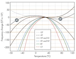
It is important to understand how oscillator manufacturers specify a device’s stability based on temperature. Timing components are typically characterized at 25°C, and developers often mistakenly assume this accuracy holds across the temperature range. Figure 1 shows how drift—and, in the long-term, accuracy—changes with temperature on various crystal cuts. As the temperature changes, the system can experience substantially greater drift, depending on how long the temperature condition persists.
For applications operating in extreme environments, such as a basestation in Alaska, the standard room temperature spec may not be useful at all. Even short exposure to higher temperatures, such as a cell-phone regularly left in the hot sun, can have a significant impact on drift. By understanding how the system will be affected by exposure to temperatures over the expected operating range, developers can anticipate and address potential long-term problems that users could experience.
Crystal Cut
Another factor affecting drift is the type of cut used for the crystal, which influences its performance at different temperatures and its overall frequency stability, among other characteristics. Many different types of crystal cuts are readily available on the market. Five common types are:
• AT cut: This cut is used for most crystals since it provides excellent temperature performance for a wide range of frequencies. It is, however, sensitive to mechanical stresses.
• BT cut: Similar to the AT cut, the BT cut uses a different angle to achieve a higher frequency-thickness constant and so be able to generate higher fundamental frequencies. It yields a parabolic frequency versus temperature behavior, though, which is inferior to the AT cut.
• XY cut: Also known as a tuning fork cut, the XY cut yields a blank well-suited for low-frequency applications because of its smaller size, reduced impedance, and lower cost compared to other low-frequency cuts. It commonly is the cut of choice for low-power applications requiring a 32.768-kHz standby clock.
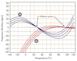
• SC cut: With the stress compensated (SC) cut, the crystal is less sensitive to mechanical and vibrational stresses. It also provides lower phase noise, superior aging, and faster warmup compared to AT cut crystals (Fig. 2). The SC cut has a third-order frequency dependency upon temperature as well, just like the AT cut, but the inflection temperature is higher, around 92°C. This means it does not suit the wide temperature range of –50°C to 100°C.
• IT cut: The IT cut has properties similar to the SC cut, though it’s better suited for applications operating at higher temperatures.
Another consideration in addition to the cut of a crystal is the type of electrode used. A crystal vibrates at a particular frequency based on the input current it receives. This current is applied over an electrode, which is made of gold or silver. Gold is more expensive than silver, but it is also more inert. The overall timing system, then, will be less affected by environmental factors such as humidity. It will also age more slowly, with the overall result of less drift.
Capacitive Load And Overdriving
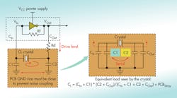
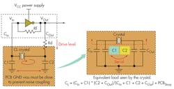
When specifying a crystal, it needs to be matched to the load that will be present. While this load comprises capacitive, resistive, and inductive components, the capacitive load affects frequency and, therefore, drift the most. Figure 3 illustrates a typical circuit showing external loads. Thus, spec sheets will often show the capacitive load, typically measured in pF. Capacitive load is one reason for the great variety of crystal components available as each capacitive load is given a different part number.
A crystal can be better matched for capacitive load once the timing portion of the design is completed. A simple way to match the capacitive load is to place a known frequency crystal down and measure the output frequency. Based on the frequency drift from the expected frequency, the correct capacitive load can be computed. Crystal manufacturers can help with these calculations and the overall matching process.
Another factor that can affect drift is how hard the crystal is being driven. Overdriving can arise when a crystal is driven greater than originally anticipated. The harder a crystal is driven over its rated maximum drive power (typically measured in µW), the faster it will age. The effects of overdriving can be significant, causing the crystal to age in a month what it would have aged in a year at its rated drive power.
A potential source of drift can be introduced whenever components are moved or rerouted on a board. Moving a crystal could change the capacitive load. Similarly, if the design was already near the limit of the crystal’s drive power, rerouting may cause the crystal now to be overdriven since changing capacitive loading will directly affect crystal drive. This can also occur when other components are moved, causing the traces interconnecting the crystal and ICs to be rerouted as well.
When design changes impact clock signal routing, both drive power and capacitive load should be recomputed to confirm that they still match the crystal that has been specified. If either has changed, a new crystal may be required. Alternatively, if a flexible timing source is being used that allows the frequency to be adjusted, such as an adjustable clock generator, capacitive changes may be more readily accommodated.
Comprehensive system testing should likely include verifying the robustness of the system in terms of the drift that still remains. This is achieved by changing the capacitance load on the board to intentionally create drift. The effect is to prematurely age the system in fast forward. In this way, the system can be tested with the equivalent of several years of accumulated drift. This technique can also be used to determine how much drift the system can handle (i.e., how many years the system can operate without recalibration) and still maintain reliable operation.
Specifying The Right Crystal
Crystal-based timing solutions are not simple products, and developers need to take the time to select the right component to keep drift in check. The following questions can help facilitate selection of the optimal crystal for an application:
• What frequency or frequencies are needed?
• What is the maximum drift the system can tolerate over its expected lifetime of operation?
• What is the typical temperature range of operation?
• How much stability over temperature is required?
• What is the load capacitance of the board?
• What packaging constraints/requirements are there?
• How much does the timing solution need to cost?
• What production volumes are going to be needed?
• How fast will components need to be available?
These are the general questions a manufacturer is going to need answered before you call for a quote. If you have this information available when you begin product selection, you can quickly get an idea of your options. In some cases, you can even use online tools such as Pericom’s XO finder (www.pericom.com/products/crystals-and-crystal-oscillators/xo/) to find the right product and generate a quote.
By understanding the effect of drift on system accuracy over time, developers can take steps to minimize drift, maintain reliability, and select a timing source that balances temperature compensation, aging, and resilience.
Reference
“Resolve The Stress Caused By High-Speed Interfaces,” http://electronicdesign.com/embedded/resolve-stress-caused-high-speed-interfaces


