Ramp Generator Uses Microcontroller Emulation Of Unijunction Transistor
This article is part of the Ideas for Design Series: Vol. 3, No. 3
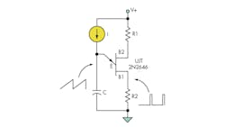
Unijunction transistors (UJTs) were common circuit elements several decades ago. A simple ramp generator could be built from a single UJT and a few other components (Fig. 1).
The operating principle is simple. The base-emitter junction is initially in a high-impedance state, and the current source linearly charges the capacitor until a breakdown voltage is reached. At that point, the capacitor discharges through the UJT base until a lower threshold voltage is reached. Then, the base-emitter connection returns to a high-impedance state, and the capacitor can recharge.
Related Articles
- LF Multivibrator Uses UJTs
- Input Clock Adjusts Frequency Of Digital Ramp Generator
- Single Supply Yields 0- To 5-V Ramp
This approach still has a few advantages over digital circuitry, as there are tradeoffs when using a digital-to-analog converter (DAC) to create a ramp. Inexpensive microcontrollers include high-resolution analog-to-digital converters (ADCs), but high-resolution DACs are expensive peripheral components. While such DACs have limited resolution, an analog ramp like one produced by a UJT has infinite resolution.
This file type includes high resolution graphics and schematics when applicable.
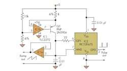
It’s possible to emulate the action of a UJT using just three I/O pins of a microcontroller and a few other components. Most microcontrollers allow their I/O pins to be dynamically reconfigured to function as either a high-impedance input or as an output. This feature is the basis for a simple UJT-emulated ramp generator.
In the microcontroller emulation, the current source is implemented by the rail-to-rail operational amplifier IC1b of a dual device and Q1, while IC1a buffers the voltage on capacitor C and provides the ramp output (Fig. 2). This capacitor is connected to both analog/digital converter pin AN0 of the microcontroller (IC2) and to its I/O pin GP1, which is initially configured as an input. A 22-Ω current-limiting resistor allows high-value capacitors to be used without damage to the microcontroller.
The pseudocode listing for the microcontroller continually monitors the capacitor voltage (see the code).
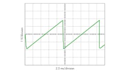
When it reaches a threshold value, it switches the I/O pin from its high-impedance input state to an output state at ground potential. When the capacitor voltage goes below another threshold value, the I/O pin is switched back to a high-impedance state, and the cycle repeats (Fig. 3). The circuit also provides a pulse synchronized with the ramp cycles, which can be used for timing and triggering.
Dev Gualtieri received his PhD in solid-state science from Syracuse University in 1974. After many years doing research for a major aerospace company, he now does computer, electronic, and embedded-systems projects at his consulting company, Tikalon LLC (www.tikalon.com) in Ledgewood, N.J. He is the author of several books, available at Amazon.
Read more articles in the Ideas for Design Series: Vol. 3
About the Author
Dev Gualtieri
Dev Gualtieri received his PhD in solid-state science from Syracuse University in 1974. After many years doing research for a major aerospace company, he now does computer, electronic, and embedded-systems projects at his consulting company, Tikalon LLC (www.tikalon.com) in Ledgewood, N.J. He is the author of several books, available at Amazon.


