This article is in Bob Pease on Analog Vol. 1 in the Analog section of the Electronic Design Library.
Members can download the PDF ebook.
On my recent seminar tour, I asked about 4000 engineers, "How many of you use noise gain?" About 2% of the people held up their hands. Sigh. Noise gain is often not very important or critical. That is one of the reasons why op amps are so popular. They tolerate almost any kind of feedback and any noise gain. You can often see that by inspection. But when it is important, things get interesting pretty fast.
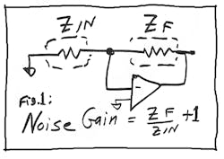
Let's start with a definition of noise gain: Noise gain is the reciprocal of the attenuation from the output of an op amp (or any feedback loop) to the input. In Figure 1, the attenuation is RIN/(RIN + RF). So the noise gain is (RF + RIN)/RIN. Or, (ZF + ZIN)/ZIN.
As I say in my lecture, it is not a good idea to try to memorize that, because that just ensures that you will forget it. But you ought to recognize the cases where life gets interesting.
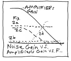
If ZF is 100 kΩ and ZIN is 1 kΩ, the noise gain will be about 100—or, technically, 101. This normally ensures that the loop is very stable because the noise gain crosses the amplifier's gain-bandwidth product at a place where there is almost never any problem (Fig. 2a). However, the name "noise gain" also reminds us that this really is the gain for the noise! So figure 1 is often used as a noise-test circuit. And, as noise does properly extend down to dc, if the op amp has a VOS of 1 mV, then the output offset will be 101 mV!
If RF/RIN is a small number, and the noise gain is not very high, the curve of Figure 2b can apply. Most op amps are happy with any noise gain from 1 to 2000. But be cautious about any amplifier that is specified for "Gain of 10 minimum." Such an amplifier has excessive phase shift at high frequencies, and it will surely oscillate if the noise gain is not at least 10 (or as stated). But, refer to NSC's App Note LB-42.
Reactances: If we add a feedback capacitor across RF, the noise gain can be high at low frequencies, but it will fall to 1 at high frequencies (Fig. 2c). Guess what? This cuts the output noise—a very popular move!
However, if your application circuit happens to have a lot of capacitance on the summing point—which might happen if you had a large photo diode or a lot of cable capacitance—then the noise gain will rise at higher frequencies. This can cause serious problems because when the noise gain rises (Fig. 2d), it tends to cross the op amp's gain-bandwidth product too steeply. And, the 12-dB per octave slope will cause severe ringing. This ringing or oscillation can usually be cured with a small feedback capacitor. The nominal value for this capacitor will be √2CIN/(GBWP × 2πRF). For a typical circuit with a summing-point capacitance of 100 pF, the CF may need to be 5 to 10 pF—not too huge.
Note, however, that while most of this analysis is computed in the frequency domain looking at Bode plots, the evaluation of loop stability is normally done in the time domain. Hit the input with a little step of current and see how well the output settles without excessive ringing.
Often, an engineer proposes to use a "tee network" for his feedback resistance to avoid having to buy a large-value resistor. I almost always say that that's a bad idea. Why? Because of the noise gain! Either due to the noise, or the bandwidth, or the drift, any tee network with a factor of more than 2 is usually a terrible idea. A noise gain of 10 or 100 or 1000 is often a terrible idea!
Next time you work with an op amp, think about the noise gain. If it is a simple case, it won't require more than a moment. But if it is complicated, it might require more than an hour! Or if you neglected to study the problem properly, you're in for days of grief!
Comments invited!
Read more article from Bob Pease on Analog Vol. 1.
About the Author

Bob Pease
Bob obtained a BSEE from MIT in 1961 and was a staff scientist at National Semiconductor Corp., Santa Clara, CA, for many years. He was a well known and long time contributing editor to Electronic Design.
We also have a number of PDF eBooks by Bob that members can download from the Electronic Design Members Library.


