Medical ultrasound imaging is a non-invasive method of viewing internal organs and structures of the human body using high-frequency acoustic waves. Sending an acoustic wave into the human body and listening to the acoustic echoes can create an ultrasound image. Given the acoustic properties of the human body, the optimum frequency range for general medical ultrasound imaging is 1.0 to 12.0 MHz.
An acoustic wave is created with a piezoelectric transducer (PZT). The PZT physically expands and contracts when a voltage is applied to it, thereby converting electrical energy into acoustic energy. High-voltage pulses are used to excite the PZT. This is done with a pulse generator, sometimes referred to as the transmitter, with amplitudes of up to ±90 V and current capability of ±2.0 A. The same PZT then is used to convert acoustic echoes back into electrical signals, which are referred to as the receive signals. The received signals are processed and analyzed to construct an ultrasound image of the transmitted path.
To better understand the principle of operation, consider a single-channel PZT (Fig. 1). During the transmit cycle, a single 5-MHz cycle of ±90 V is generated from the transmitter and applied across the PZT. The PZT creates a 5-MHz acoustic wave that travels into the body, and the receiver starts listening for echoes. Acoustic waves travel on the average of 1.54 mm/μs within the human body.
1. Shown is a typical single-channel piezoelectric transducer (PZT).
To create an image of an object that is 10 mm away from the PZT, a time duration of 10 mm/(1.54 mm/μs) = 6.49 μs is required for the acoustic transmit wave to reach the object. Another 6.49 μs of time is needed for the acoustic echo to reach the PZT from the object. The signal received at 12.98 μs corresponds to an object 10 mm away from the PZT. The time duration for the received cycle is therefore longer when imaging objects further away from the PZT. Once all echoes are received, one line of image can be constructed.
The receiver is a high-performance, low-noise, low-voltage device that can be easily damaged if the high-voltage pulses from the transmitter are applied to its input. Fig. 1 shows a T/R SW block—a transmit/receive switch—that’s used to block the high-voltage transmit pulse, but allows the low-voltage receive signal to pass into the receiver’s input. The receive voltage is typically less than ±500 mV.
To create a two-dimensional image, an array of PZTs is needed. An ultrasound probe is used to house the array of PZTs. There are many different types of ultrasound probes, such as abdominal, cardiac, and pediatric probes, among others, and all are specifically designed for various applications. The number of PZTs can vary depending on the probe type, ranging from 128 PZTs to 512 PZTs. An array of 192 PZTs will be used as an example for this article.
Use of High-Voltage Analog Switches
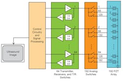
Figure 2 shows a basic medical ultrasound system driving an ultrasound probe with 192 PZTs. High-voltage analog switches are used to multiplex the transmitter, receiver, and T/R switch set to different PZTs.
2. High-voltage analog switches are used in this medical ultrasound system that’s driving an ultrasound probe with 192 PZTs.
The example in Fig. 2 has 64 sets of transmitters, receivers, and T/R switches. Each set drives three PZT elements. Its 192 high-voltage analog switches are arranged whereby groups of 64 PZT elements are being driven. The analog switches route the 64 sets of transmitters, receivers, and T/R switches to drive PZT 1 to 64. The 64 transmitters send high voltage pulses into PZT 1 to 64. The system waits until it receives all echoes from PZT 1 to 64.
For the next cycle, the analog switches reroute the 64 sets of transmitters, receivers, and T/R switches to drive PZT 2 to 65. The 64 transmitters send high-voltage pulses into PZT 2 to 65, and the system waits to receive all echoes from PZT 2 to 65. This routine of transmitting, receiving, and rerouting repeats with the analog switches rerouting the transmitters, receivers, and T/R switches by one PZT increment at a time. Once all 192 cycles are completed, one frame of image can be constructed in about 50 ms.
Without the use of high-voltage analog switches, 192 transmitters, receivers, and T/R switches are required to drive the 192 PZTs. With the use of high-voltage analog switches, the number of transmitters, receivers, and T/R switches is reduced by a factor of three, saving cost, power, and size.
Advantages and Benefits of MPS High-Voltage Analog Switches
Figure 3 shows the basic differences of using conventional analog switches versus analog switches developed by Monolithic Power Systems (MPS). Conventional high-voltage analog-switch ICs require two high-voltage power supplies, +100 V and −100 V, for proper operation. The high-voltage pulses going through the analog switch must be within 10 V of the high-voltage supplies. For ±100-V supplies, the maximum transmit voltage is ±90 V. Additional circuits are needed to generate these two high-voltage supplies, since they’re not required elsewhere in the system. These are dedicated power supplies for the conventional high-voltage analog switch ICs.
3. A conventional analog switch is compared with an analog switch developed by MPS.
Safety concerns come with such high-voltage supplies. Protection circuitry is needed to eliminate the risk of shock under various fault conditions, such as damaged insulation. Power-up and power-down sequencers should also be considered for safe operation. The voltage level on the high-voltage supplies must be monitored to inhibit the transmitter if the voltage levels are too low.
On the other hand, the MPS MP4816A IC is a 16-channel, high-voltage, analog switch that uses a 10-V supply instead of two high-voltage power supplies. This removes the need for the two high-voltage power supplies, which reduces the complexity of the power-supply design and lowers power dissipation. The support circuitries associated with the two high-voltage supplies, such as power-up and power-down sequencers and voltage monitors are also eliminated. The end result is a system with lower cost, reduced size, and increased reliability.
High-Voltage Analog Switches in the Probe Head
Using analog switches configured as a 1-to-3 multiplexer inside the ultrasound probe head with 192 PZTs reduces the number of coaxial cables by a factor of three. Instead of 192 coaxial cables, only 64 coaxial cables are needed for the PZTs, plus 10 or fewer additional coaxial cables for the logic supply and I/O interface.
Reducing the number of coaxial cables results significantly lowers cost for the ultrasound probe head, as coaxial cables are very expensive, as is the labor cost to connect them. An added user benefit for the sonographer is that the probe head becomes more maneuverable, creating less fatigue.
The probe head is generally severely limited spatially and thermally. The housing is waterproof, as it must be able to withstand being submersed in alcohol for sterilization after use, making it difficult to remove any heat being generated inside the probe head. Eliminating the high-voltage supplies reduces power dissipation and wipes away any safety concerns of high-voltage dc lines on the coaxial cables.
Conclusion
High-voltage analog switches are commonly used in medical ultrasound systems, both in the system and in the ultrasound probe head. The design of MPS’s high-voltage analog switches eliminate the need for high-voltage supplies, simplifying the power-supply design, lowering overall system cost and size, and increasing reliability.


