Download this article in PDF format.
We’ve been waiting for a long time and now it’s being implemented widely—namely, artificial intelligence (AI). From automatic factories, self-driving cars and trucks, to robot chauffeurs, we are now seeing how AI will make automatic machines more efficient, profitable, and improve our lives. And, at the center of these automatic machines and automobiles is their ability to measure position and motion accurately.
There are many ways to measure position, but one rapidly growing technology is the inductive position sensor. Accuracy, noise immunity, and cost-effectiveness are some of the benefits of this technology. Below, some misconceptions about inductive position sensors are dispelled alongside a comparison to other sensor technologies such as Hall-effect and magnetoresistive sensors.
1. Inductive sensors use inductance to measure position.
The label can be confusing, but the truth is, inductive sensors do not measure inductance. Instead, they use the electromagnetic induction of a magnetic field in a metal target along with the well-known properties of an air core transformer and Faraday's law to accurately locate the disturbance of this magnetic field by the target. It may sound complicated to many of us who have forgotten all we learned about electromagnetic field theory from school. Simply put, though, inductive sensors measure the disturbance of a magnetic field by a conductive target.
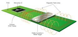
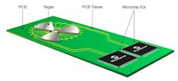
In addition, this magnetic field isn’t generated by a permanent magnet, which is needed for Hall effect sensors and magnetoresistive sensors. Instead, it’s generated by the primary winding of a transformer (Fig. 1).
1. An inductive position sensor generates a magnetic field using transformer windings.
Two secondary coils are used to detect this magnetic field, and just like with a transformer, we use Faraday's law to convert this field into a voltage. A metal target placed into this magnetic field will induce eddy currents that oppose the magnetic field and drop the field strength to zero at the target. By being placed in different physical locations, the two receiving coils will detect a different voltage. The position of the target can be calculated by simply calculating the ratio of these two receive coil voltages.
2. Inductive position sensors aren’t accurate.
This is an easy myth to dispel because inductive position sensors are very accurate, excelling at higher temperatures where other magnet-based systems have trouble. The big reason for the accuracy of inductive position sensors is that they don't rely on the nonlinear nature of the permanent magnet. Instead, they’re just looking for the disturbance of the self-generated magnetic field.
Thus, errors below ±0.1% over the full measurement range can be achieved at room temperature. Errors below ±0.3% are achievable over temperature and with air-gap variations between the target and sensor. In addition, the complete algorithm is designed to either eliminate temperature variation or minimize its effect.
For example, the inductive position sensor will excite the magnetic field at a frequency between 1 and 6 MHz, but it uses a LC oscillator. Though both of these quantities may change with temperature, this has no impact on the position.
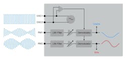
The reason is that the secondary receive channels use synchronous demodulation (Fig. 2), which is a function of the primary oscillator. This drift will not have any impact on the amplitude of the received signals. Other than temperature, metal objects near the sensor may affect the magnetic field.
2. A synchronous demodulator can be used to eliminate differences due to temperature fluctuation.
As a result, some level of calibration is required, but the calibration doesn’t change with temperature. For example, Microchip Technology’s LX3302A uses eight calibration segments. In addition, 13-bit analog-to-digital converters (ADCs) and 32-bit processors help to eliminate any calculation and quantization error that may occur, providing 12 bits of output resolution over the measurement range.
3. Inductive position sensors are expensive.
It isn’t common to get the best of both worlds—high performance at a reasonable cost—but inductive sensors deliver here as well. While Hall-effect and magnetoresistive sensors require that a permanent magnet is manufactured to the proper tolerance and strength to get decent accuracy, inductive sensors need only a piece of metal as a target, saving the user the price of the magnet.
Though the PCB will need to be larger to route the sensor traces, this usually costs significantly less than the cost of the magnet. And if you have additional PCB space, this portion can be free. Thus, the inductive position sensor is a more cost-effective solution over Hall-effect and magnetoresistive solutions because it provides magnetic-field sensing without a magnet.
4. Inductive position sensors are sensitive to an external magnetic field.
Today's automatic machines are creating more stray magnetic fields than ever before, causing issues with Hall-effect and magneto-receptor sensors. Inductive positions sensors use active demodulation to reject these stray fields (Fig. 3).
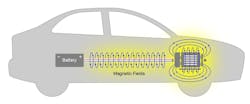
3. A motor and high current can generate high stray magnetic fields.
Next-generation electric cars may have several hundred amps running from the batteries to the traction motor. In addition, most cars have more than three brushless dc (BLDC) motors for moving the car, the electronic power steering, and the brake assist motor. All these systems generate stray magnetic fields.
Due to the rapid rise in these stray magnetic fields, new specifications are requiring more immunity tests at higher magnetic fields. In the automobile industry, car electronics are now subjected to a 4-mT (millitesla) dc field during electromagnetic-compatibility (EMC) qualification, and false readings in any of the safety-critical sensors—power steering, accelerator pedal, traction rotor position—cannot occur.
The beauty of inductive position sensing is that it’s immune to these noises because it actively filters only the frequency it requires to sense. Because inductive position sensors don't use any magnetic material, they don't pick up any dc magnetic field. In other words, Faraday's law is zero for a static magnetic field.
In addition, the synchronous demodulator described above will filter out other frequencies above and below the primary excitation frequency, much the same way as you can select one AM radio station when the antenna picks up the complete AM band. This same type of rejection isn’t possible with Hall-effect and magnetoresistive sensors.
5. Inductive position sensing is new technology.
Inductive position sensors use a PCB as the sensor and a piece of metal as the target. While this may be a new way to implement sensing, the technology is well-established. The linear voltage differential transformer (LVDT) is a very close relative to inductive position sensing. The LVDT will use a primary coil and two secondary coils to detect the position of a metal shaft in robotic applications (Fig. 4).
4. The linear voltage differential transformer (LVDT) is a very close relative to inductive position sensing. It’s able to utilize the motor windings to detect changes. A rotor target can be used in conjunction with a PCB-based sensor.
Inductive position sensors use much of the same techniques to reduce the windings to just a PCB. Magnetic resolvers, the rotary version of the LVDT, also use similar techniques. Once again, instead of a transformer-looking metal structure, inductive position sensors perform the same function that can be achieved by using traces on a PCB. To sense position, LVDT, resolver, and inductive sensors take the ratio of two voltages as induced by the disturbance of the magnetic field by a conductive element.
6. Redundant inductive sensors require double the space.
Critical automotive and industrial applications often need redundancy to provide the highest level of safety. By optimizing the layers of a PCB and some intelligent primary-winding techniques, a dual sensor doesn’t require double the PCB space. Instead, both sensors can be in the same PCB space (Fig. 5). In this case, they share the same magnetic field, coupled loosely by a magnetic field, and still provide galvanic isolation. The secondaries can go to the two ICs, which will then output independent and redundant position, improving the safety of the application.
5. Redundancy sensors can share the target sensing device, thereby reducing the overall size of a redundant system.
7. Inductive position sensors can only handle small linear measurements.
Inductive position sensors are able to measure linear positions up to many different lengths. The best accuracy occurs when the sensor’s length is close to the approximate desired measurement range so that the output resolution can be scaled over the shortest distance. This sensor length can range from 5 mm to 600 mm and beyond for practical applications. Any limitations in length have to do with the ability of the oscillator being able to generate the correct LC resonant signal. In all cases, the operating principle is the same: A magnetic field is generated, and the disturbance is detected. Linear measurements are a definite advantage of this technology, and the sensitivity can be achieved by a single measurement principle over many practical measurement ranges.
Alternatively, a Hall-effect sensor may require several Hall-effect sensors to be multiplexed as the magnet is moved from one location to another. The crossover handling of this multiplexing is complicated and may be affected by temperatures. An inductive sensor doesn’t suffer from this difficulty and can be made to output a linear measurement that matches the application’s requirements.
8. Inductive position sensors can only measure linear measurements.
While linear measurement is a definite advantage of this technique, inductive position sensors can also measure rotary and arc sensing target trajectories with the same benefits of higher accuracy and better noise immunity. Car pedals, air valves, water valves, and rotor position are all sensing examples that can use inductive-sensing technology.
Think of a 360-degree rotary sensor as just a linear sensor where the ends are curved to meet on another. It turns out that rotary inductive position sensors are the most accurate sensors because the generated magnetic field can be very uniform at every radius. Linear, arc, and rotary measurements are all possible with this technology.
9. The target material must be magnetic.
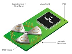
The inductive position sensor detects a change in the magnetic field, and this magnetic field is disturbed by a metal target, but no magnetic material is needed. Anything that conducts current, allowing an induced eddy current to flow, will induce this disturbance (Fig. 6). Magnetic materials like iron are conductive, so they can also be used. However, the target metal will have better detection distance and lower supply current if it’s made of a good conductor like copper, aluminum, or steel.
6. Eddy currents can be induced in a metal structure.
10. Inductive position sensors need to be programmed over input power.
In an automobile, many sensor applications are in modules that are connected to the engine control units through a set of wires. For a sensor, this normally consists of a power line, ground line, and an output pin. Being able to calibrate the module over the power pin ensures that no additional connections to the sensor PCB is required, saving cost and assembly issues.
However, some applications require a microcontroller. This is where embedded applications would like to program the sensor using another microcontroller, not a dedicated test system. Microchip’s LX3302A has this function and capability, allowing it to be programmed over the GPIO pins.
11. You’re on your own with the design.
Not too long ago, a solid knowledge of magnetic fields and access to a high-end finite-element simulation suite or lots of trial-and-error was required to get good results. Today, IC vendors are providing this service for their customers with evaluation boards and kits that take you from concept to actual PCB trace simulations. Some vendors will even provide simulation results estimating the error you will have with a sensor before the PCB is tested. Microchip offers this assistance to help with your PCB designs.
These 11 myths show how inductive position sensors compare to Hall-effect and magnetoresistive sensors, illustrating the accuracy, immunity to stray magnetic noise, and cost-effectiveness. Are you ready to try this technology with your next AI-position sensing product?
Mark Smith, Ph.D., is Product Line Marketing Manager, Mixed-Signal and Linear Division, at Microchip Technology.
