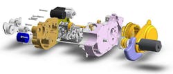
At the beginning of 2019, I purchased a Creality CR-10S S5 3D printer to make prototype parts for a motorcycle engine design I’ve been working on for decades (Fig. 1).
1. A redesigned Sportster motorcycle engine using parts from 1952-1984 era motors. Dubbed OSARM, for Open-Sport aftermarket replacement motor, I have worked on it for 20 years as an open-source design project.
Since the engine is almost two feet long, I needed a large printer, and the 500- × 500-mm working area of the Creality printer was one of the few inexpensive printers large enough to make my prototypes. Here's a video of my impressions of the printer:
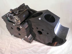
In the video, I discussed the quality issues I had, the design problems of the printer, and my own ignorance and mistakes. While I did find some quality problems with the printer, I was amazed with the prototype engine cases I printed out (Fig. 2). I plan on having these machined out of aluminum, which will cost many thousands of dollars per part. The aluminum cost alone is about 500 dollars for a case-half. The cost of the 3D-printed plastic is 20 dollars.
2. A plastic prototype of the OSARM engine made with a cheap 3D printer can prove out the design before machining aluminum parts.
I designed the engine in SolidWorks, and CAD (computer-aided design) does help you see problems. Still, there’s nothing like holding a real part in your hand to see how it works and assembles to other parts. The 500- × 500-mm printer cost me about 900 dollars in 2018, lately selling for $720.
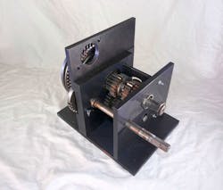
After working the bugs out and learning the principles of printing, my first project was to print a fixture for the transmission of my new design (Fig. 3). The design uses older Harley Sportster engine components, ranging in age from 1952 to 1984. The new case is my attempt to solve some systemic problems in the older design.
3. This transmission jig is also 3D-printed. It verifies the design before committing to much more expensive aluminum parts.
The Jig is Up
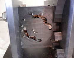
The new design requires a new shifting mechanism, so I can move the transmission closer to the crankshaft. This reduces engine length, and makes the primary chain shorter, obviating the need for a tension mechanism. When I printed out the small rotating shifter plate, I never expected it to fit into the holder I had printed, but it worked perfectly (Fig. 4).
4. The rotating circular plate that operates the shifter forks fits into its holder exactly. The right fork boss not being at the end of its slot reveals a design problem.
Being able to prove out the shifter jig, before making the parts in aluminum, gave me the feeling that the printer had already paid for itself. I found several problems and I can correct them before using the aluminum jig to make sure the new shifter mechanism works right. Companies like Protolabs offer painless computer-numerical-control (CNC) quoting, so that will be my first stop at making the jig out of aluminum. I’ve had good results using them for plastic molded prototypes, so I’m hoping their CNC service works out as well.
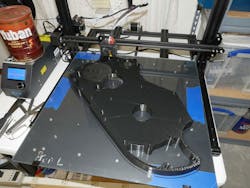
The results of the transmission jig encouraged me to print the engine case parts (Fig. 5). I learned about printing parameters as I went. To make a printed part, you take a solid model from a CAD package like SoildWorks and open it in the “slicer” program. This computer-aided-manufacturing (CAM) program generates the toolpaths for the 3D printer in G-code, similar to the G-code used by CNC machines. One popular and free slicer is Cura. Based on advice from a mechanical engineer friend, I paid $150 for Simplify3D, another popular slicer program. The fact that Simplfy3D stores both the model and the printer settings in the G-code has made me glad I paid for it.
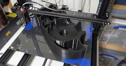
5. Here, an OSARM case-half is being made in the Creality CR-10S S5 printer. The blue tape is truing the glass bed flat. The gray circle at the back of the part is a removable support structure for a hollow area below subsequent layers. The inside of the part is not printed solid, but rather, it’s a matrix called infill. To get the part to print in under four days, I set the infill at 10% in the Simplify3D slicer software.
There was all the usual suffering with software. SolidWorks had default stereolithography (STL) settings that were a bit course. I made the permissible deviation from true to less than 0.005 inches, and the .stl file size ballooned to 98 MB. Simplify3D would open this file, but it would hang when I set it up to make thicker outer shells for strength. I also wanted the thicker shells so I could tap several holes in order to bolt my mock-up engine together.
Creality Reality
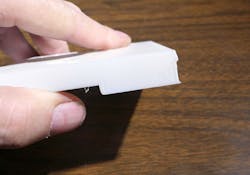
The video I made details some of the travails I had getting good prints. The worst initial problem was that Creality shipped the printer with the Y-axis pulley slightly loose. This cause my first parts to have level shifting in the Y direction (Fig. 6). I went through a whole spool of plastic filament thinking the stepper motors were skipping from loads and accelerations before I realized I just needed to snug up the pulley setscrews.
6. A half-sized trial part of the transmission jig exhibits level shifting in the Y-axis. This was caused by a loose pulley.
Besides a few quality-control issues, the Creality did have a couple design shortcomings. While the bed is 500 × 500 mm, the heater under the bed is much smaller, about 300 mm square. You need the heater to get the bed up to 65°C or so, which makes the plastic filament stick to the glass bed. After the part is printed, the bed cools off and the part pops off. Full-sized bed heaters are available.
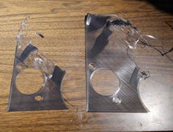
Another shortcoming is the need to level the bed before every print. I found I needed to first tram the X-axis extrusion to be level with the frame of the machine. Then there are four thumbscrews with spring mounts under the four corners of the bed. It’s critical to level the bed so that the first layer of plastic filament goes down uniformly. I initially had the gap too close, and it caused the filament to build up pressure until it squirted out in unsightly patches that interfered with subsequent layers (Fig. 7).
7. Two failed first-layer prints of the transmission jig. I had set the print nozzle too close to the bed. The plastic filament would build up pressure, and then squirt out in patches that propagated into large unsightly patches. That other areas of the first layer are almost transparent is an indication the spacing was too close.
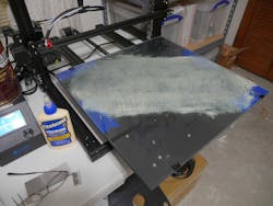
One thing I did learn is that using the heated bed with the stock glass platen is the smart way to go. I tried tricks advocated on the internet, like thinned Elmer's glue or glue sticks (Fig. 8), and the lack of control and consistency convinced me it was a losing proposition, I did not even try Aqua Net unscented hairspray, another trick advocated on the internet. My feeling there was that it was both an uncontrolled operation and that it would make a mess and get all over the moving parts of the machine.
8. I tried to cure warping problems by coating the bed with white glue diluted with water. The results were unsatisfactory, as was using glue sticks.
Just Do It
I encourage anyone interested in prototyping with 3D printing to just go out and buy a printer. I spent way too much time researching and theorizing. I thought I had to be a “cool guy” that had dual filament extruders for different colors or for water-soluble support material like PVA plastic. Turns out the support structures that Simplify3D auto-generates in the PLA plastic work just great. The zig-zag structures break off cleanly, even when they are inside horizontal holes in your parts. I also thought I wanted a direct extruder, instead of using a Bowden tube type. The Bowden type worked great; putting the stepper motor on the moving part of the X-axis only adds weight and mass to something you want to keep as light as possible.
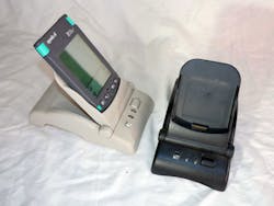
I’m not new to 3D printing. I used a service called Forecast back in 2001 to make a STL case for a point-of-sale terminal I designed (Fig. 9). It allowed the startup I worked for to show angel investors real hardware. Companies like Protolabs and Stratasys also offer 3D printing that can be faster than you might do in-house.
9. These are two prototype SLA point-of-sale terminals made in 2001. Stereolithography gives better surface finish, and better strength, but the machines are too expensive to have at home.
When I was in my theoretical phase, I convinced myself that I had to send things out since I needed to do selective laser sintering (SLS) to make the parts. Since SLS melts the plastic with a laser from a bed of powdered plastic, you don’t need support structures in the part. You can just send the solid model to a proto shop, and although the surface finish is not very good, it comes back form-fit-and-function.
See, I theorized all this without every printing a part. Once I saw how good Simplify3D made support structures, I knew I could use cheaper simpler fused-filament (FF) printers, and I could do it in my office rather than sending it out.
Plastic vs. Metal
Now there’s a lot of hype about 3D printing being used for high-volume manufacturing. This is a sketchy proposition. The problem with 3D printing is that the plastic has much poorer properties than an injection-molded or machined plastic part. Just as bad, the time to make a single part is excessive. You are tying up a piece of capital equipment for a long time to make a single part. Contrast this with sheet metal. Sure, the steel dies will cost hundreds of thousands of dollars, but once you pay for the dies, you can stamp out a part every few seconds.
I worked at General Motors when they came out with the Pontiac Fiero. It was a plastic-bodied car, that unlike the Corvette, was meant for high-volume manufacturing. The first problem was that the parts were not as repeatable as sheet metal. So GM made a gigantic machine that would machine location points for the plastic panels on the car. Then they ran into that same cycle-time problem. You have to heat the die, then squirt in the plastic, and then cool the die with water jackets. It took over 30 seconds per panel.
So, you have one-million-dollar machine that makes two parts a minute, versus a stamping press that can make 30 parts a minute. Add to that the cost of the machine that trimmed the mounting points on the car, and you are tying up a lot of capital expense for revenue that does not come in nearly as fast.
There’s a lot of valid interest in printing metal parts, where you sinter the part after printing to give it properties as good or better than a machined part. This is a valid process, but it’s confined to high-value, low-volume production in aerospace right now. Until the cycle times come down, or the machines get as cheap as my Creality printer, there’s little chance the parts will be in consumer products.
There are 3D printer farms that have hundreds of printers working in parallel to get the production up. You can use cheaper consumer machines in those settings, but now you need lots of floor space. As a result, you have a sizable plant cost to go with the capital expense of all those printers. Don’t forget the labor to feed and care for the printers as well.
Cycle times are an interesting difference in molding plastics and metals. A metal die casting is a very fast, very high-pressure event. A mechanical engineer pal told me it’s almost as if the metal is exploding into the die. It will cool a lot faster as well, having better thermal conductivity. A plastic injection mold is a slower, more leisurely event. The plastic squeezes into the mold much more slowly, and you need a significant dwell time to let the plastic harden enough so that it does not warp when you eject it from the mold.
It’s all about cost—that’s the beauty of engineering versus science. What I have learned is that while high-volume manufacturing may not be applicable to 3D printing, prototyping and visualization are a perfect application. Feel free to watch a few YouTube videos and go out and buy a printer, or maybe build one of your own from scratch.
About the Author

Paul Rako
Creative Director
Paul Rako is a creative director for Rako Studios. After attending GMI (now Kettering University) and the University of Michigan, he worked as an auto engineer in Detroit. He moved to Silicon Valley to start an engineering consulting company. After his share of startups and contract work, he became an apps engineer at National Semiconductor and a marketing maven at Analog Devices and Atmel. He also had a five-year stint at EDN magazine on the analog beat. His interests include politics, philosophy, motorcycles, and making music and videos. He has six Harley Sportsters, a studio full of musical instruments, a complete laboratory, and a video set at Tranquility Base, his home office in Sun City Center Florida.
