Modeling on Mondays: GAP/R K2-W Vacuum-Tube Op Amp SPICE Modeled Performance (Part 5)
What you’ll learn:
- The K2-W vacuum-tube op amp has an LTspice-simulated open loop gain of 27,000.
- The modeled K2-W input impedance is >100 MΩ.
- The LTspice modeled result shows 1.00 nA of input current.
Most engineering analysis and design is about modeling and measurement. The first commercially available operational amplifier, Philbrick’s vacuum-tube-based GAP/R K2-W, became the eventual focus of a recent series of articles, taking us from an introductory review (or, perhaps, preview) of modeling common electronic devices1 through modeling vacuum-tube (VT) triodes in SPICE,2-3 on to establishing a SPICE model (with the LTspice files included as part of the writeup for Part 4 of this series, here) for the K2-W.4
Early SPICE simulations based on that model provided reasonable results. Therefore, the next step is to carry out further simulations to see how the model performs with respect to the specifications given in the K2-W data bulletin.
Initial Evaluation
A search will turn up multiple versions of the data bulletin for the GAP/R Model K2-W operational amplifier, with minor variations. The list of specifications is short, and our initial evaluation, which is done by simulation only, selects from that list. The particular version of the data bulletin referred to in the following is given in Reference 5; a second version is given in Reference 6. For each item in the list below, the manufacturer’s specification is given first. Results from the evaluation via SPICE follow, along with comments, when appropriate.
Specifications
Input Bias:
- Positive input should be made to operate about 1.5 V high at balance, normally requiring adjustable external bias.
- The version of the data bulletin in Reference 6 states, “Adjustable from 0.9 to 1.7 volts between Pin 1 and 2 (Pin 1 positive with respect to Pin 2).”
- Pease recalled7 that the K2-W’s input offset voltage was ‒1.5 V (design center) ± 0.25 V typical, ±0.5 V maximum.
- Input offset voltage Vos was the first specification checked; we needed to bias out its effect for every other configuration used in the evaluation. Since Vos is so large, finding its value is simple: Place the K2-W in a unity-gain noninverting configuration with its noninverting input tied to ground instead of to a signal source. Then read the voltage appearing at the K2-W’s output; that voltage is Vos.
- For our K2-W model, Vos = ‒1.54209 V, which is at roughly design center.
Gain:
- 15,000 DC, open loop.
- Benchtop setups to measure DC open-loop gain are somewhat fussy―they’re tedious, can be noisy, need to have the effect of Vos very carefully canceled, and can easily lead to results having poor accuracy and large variance. Fortunately, extreme accuracy and precision are typically not needed for this specification. Furthermore, there are methods that give AC open-loop gain over a desired range of frequencies while circumventing the Vos issue. The AC open-loop gain at a very low frequency is essentially the same in value as the DC open-loop gain.
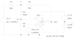
- A straightforward setup to measure AC open-loop gain appears in Figure 1. The configuration is that of a basic inverting amplifier, but with a twist that involves R3 and R4 in a simple voltage-divider arrangement. The voltage at the inverting input of the op amp is R3/(R3 + R4) times the voltage appearing at point x. The open-loop gain at the operating frequency of source V_in is just Vout /Vx scaled by (R3 + R4)/R3. The bias voltage Vos_null is set to eliminate, as completely as practicable, the effects of Vos on the output.
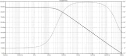
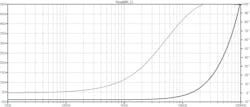
- The results of a sweep from 10 mHz to 1 MHz appear in Figure 2. The open-loop gain at very low frequencies is about 88.6 dB, or 27,000. Note the dominant pole at 33 Hz.
- The results of a sweep from 10 mHz to 1 MHz appear in Figure 2. The open-loop gain at very low frequencies is about 88.6 dB, or 27,000. Note the dominant pole at 33 Hz.
Output Impedance:
- Less than 1 kΩ open loop; below 1 Ω fully fed back.
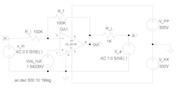
- Figure 3 gives the setup used for measuring Zout with the op amp in an inverting configuration. Zout is determined by the ratio of the output voltage vout to the current through R_L. The input source to the op amp is turned off, and V_a and R_L are chosen so that they don’t overdrive the op amp.
- Figure 4 shows Zout vs. frequency for the G = ‒1 inverter shown in Figure 3. At 10 Hz, |Zout| ≈ 1.09 Ω. (With the op amp placed in a unity-gain noninverting configuration, |Zout| ≈ 0.545 Ω.) According to the method used to measure, |Zout| is much greater than 1 kΩ when run open loop. However, for a closed-loop gain of about ‒890 or less, |Zout| stays below 1 kΩ at low frequencies.
Voltage Range:
- ‒50 Vdc to +50 Vdc at output and both inputs.
- Figure 5 shows that the output can swing at least ±50 V. The K2-W was set up as a G = ‒1 inverting amplifier, and a 50-kΩ load was attached. A 1-kHz sinusoidal input having amplitude of 75 V was applied. Note that the output is clipped at about ‒75 V; no clipping is apparent on the positive side.
Output Current:
- ‒1 mA to +1 mA, driving 50-kΩ load over full voltage range.
- See Figure 5 for evidence that this specification is met.
Power Requirements:
- 4.5 mA at +300 Vdc; 4.5 mA at –300 Vdc.
- With the K2-W in a G = ‒1 inverting configuration, with offset-null bias voltage attached, and with no load, a DC-operating-point run gives the quiescent supply current required as 4.29 mA at +300 Vdc and 4.08 mA at ‒300 Vdc.
Input Impedance:
- Above 100 MΩ
- Differential input impedance Zd of a VT-based amplifier such as the K2-W with both its input grids “naked” is very difficult, and even the results from a simulation set up to measure it should be taken lightly. Suffice to say, though, one should expect Zd to be in the hundreds-of-megohms range. A quick simulation run gave a value of 1.1 × 10¹³ Ω, so it’s safe to say that our model meets the specification given by Philbrick.
Input Current:
- < 0.1 μA, for either input.
- The same simulation used to obtain the power requirements gave the quiescent current for each input as 1.00 nA.
Response:
- 2-μs rise time, with bandwidth over 100 kHz when used as an inverter.
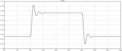
- Figure 6 shows the response of the K2-W, when placed in a G = ‒ 1 inverting-amplifier configuration with no load attached, to a 1 V p-p pulse applied to the amplifier’s input. Both the 0-100% rise time tr and the 0-100% fall time tf are approximately 0.75 μs.
- The frequency response in the stated configuration was shown previously in Figure 3 of Reference 4, which indicated a bandwidth of greater than 100 kHz. (The magnitude response was essentially flat out to 100 kHz, peaked at roughly +4 dB just above 400 kHz, and dropped to ‒3 dB at about 650 kHz. The value of the load resistance R_load has negligible effect on the frequency response, but the amount of resistance R_b in series with the bias voltage has noticeable effect.)
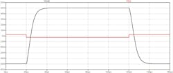
- If the gain is changed to ‒20 by setting R_i = 50 kΩ and R_f = 1 MΩ, the response to a 5 V pulse at the input is approximately critically damped (Fig. 7). This run was performed because the same measurement had been done on a real K2-W (see Reference 8), and the results of the simulation compared quite favorably with the benchtop measurements. Both the 5-95% rise time and the 5-95% fall time obtained via the simulation were just under 12 μs. From the photo in Reference 8, the rise time and the fall time are very roughly 15 μs for K2-W on the bench. Both the frequency response and the step response of the circuit depend on the value of R_b and, to some extent, the value of R_load.
The Next Step: in panchina
The K2-W SPICE model performed well in all of the simulations run to compare its characteristics and performance with specifications in the GAP/R K2-W data bulletin. The obvious next step is to make a few measurements on an actual K2-W, in circuito, on the bench to aid in verifying the adequacy of the model.
In the sixth and final part of this series, we’ll round up a functional K2-W, a pair of well-regulated 300-V power supplies, and the usual benchtop instruments; build a simple test jig; make the measurements; and see what we can learn!
Stay tuned for Part 6, which will be coming on Jan. 6, 2025!
References
1. Stephen A. Dyer, “SPICE Modeling of Common Active Devices—An Overview,” Electronic Design, Nov. 18, 2024.
2. Stephen A. Dyer, “An Intro to Simulation of Vacuum-Tube Triodes in SPICE,” Electronic Design, Nov. 25, 2024.
3. Stephen A. Dyer, “Nonlinear SPICE Models of Vacuum-Tube Triodes” Electronic Design, Dec. 2, 2024.
4. Stephen A. Dyer, “The GAP/R K2-W Vacuum-Tube Op Amp in SPICE,” Electronic Design, Dec. 9, 2024.
5. “Model K2-W Operational Amplifier,” (data bulletin).
6. “Model K2-W Operational Amplifier,” (data bulletin).
7. Robert A. Pease, “What’s All This K2-W Stuff Anyhow?,” Electronic Design, Jan. 5, 2003.
About the Author
Stephen A. "Jack" Dyer
Professor Emeritus of Electrical and Computer Engineering, Kansas State University
Jack Dyer is Professor Emeritus of Electrical and Computer Engineering, Kansas State University. He holds degrees in physics, electrical engineering, and engineering, and he spent most of his career as a faculty member, having taught over 80 different courses in mathematics, physics, electrical and computer engineering, entrepreneurship, and music. Jack’s research was broadly in digital communication systems, digital signal processing, instrumentation and measurement, spectrometry, and numerical methods, but his fun has been in analog electronics. His consulting practice centered largely on engineering forensics and assistance in product design.
When not resto-modding a Hammond or an attendant Leslie speaker system, he’s either playing in a band or searching for opportunities to bore holes in the sky via helicopter, gyroplane, or fixed-wing aircraft.
