Ka-band Transceiver Implements MIMO and Beamforming for 5G
This file type includes high resolution graphics and schematics when applicable.
My choice for the best communications product this year is Anokiwave’s AWMF-0108 Ka-band 5G transceiver. This new IC promises to speed up and simplify the design of Fifth-Generation (5G) cell site equipment.
Even though the cellular system is still under development, great progress is being made. Field trials are being conducted and some standards are still being debated and evaluated. In addition, 5G spectrum allocations are ongoing. While full deployment is not expected until 2020, some systems will go live before that.
Technology Advances Push 5G Development
There are several drivers for 5G development. These include the desired capacity expansion of cellular service, a shortage of LTE spectrum, and the demand for higher data rates to support greater video use. Other drivers are a desire to implement a wireless broadband system and a way to support the billions of new Internet-of-Things (IoT) devices that are expected to come online in the coming years.
Here is a summary of what we know about 5G at this time:
- The 5G system will be a network of small cells. These will be mounted on walls, lampposts, and small masts, as well as indoors. Range will be a maximum of 100 to 200 meters.
- Modulation will be some form of OFDM for downstream and a single carrier variant for uplink.
- Access will be TDD.
- Use of millimeter wave (30 to 300 GHz range) spectrum to achieve needed bandwidth.
- Data rates will approach 1 Gb/s with typical averages much less than 500 Mb/s.
- Target latency < 1 ms.
- Massive MIMO. Multi-user MIMO. Antenna arrays from 16 to 1,024 elements for high gain and directivity.
- Active beam steering phased-array antennas.
The real secret to making 5G work is the use of MIMO and phased-array beam steering. Beam steering focuses the beam to produce boosted transmitter power and higher receiver gain and sensitivity. It also increases link reliability and minimizes interference with nearby cells. The real challenge of 5G design is implementing the MIMO and beam steering. The new Anokiwave chip solves this problem.
The 5G IC Solution
The AWMF-0108 is the first commercially available Ka-band quad core IC transceiver for 5G communications. It is designed for fixed and mobile access networking equipment. The AWMF-0108 operates in the 27.5-30 GHz frequency range, one of the new bands recently allocated by the FCC for 5G. This new IC supports four Transmit/Receive (Tx/Rx) radiating elements and includes all necessary beam steering controls for 5-bit phase and gain control. The device operates in half duplex, enabling a single antenna to support both Tx and Rx operation. Anokiwave’s patent-pending IP blocks enable low-cost hybrid beam forming for multi-antenna arrays with high energy efficiency.
Additional features of the AWMF-0108 include gain compensation over temperature, temperature reporting, Tx power telemetry, and fast beam switching using eight on-chip beam weight storage registers.
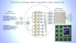
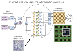
Figure 1 shows a simplified diagram of the AWMF-0108 within the dashed circle. Note the 64 element phased-array antenna, 32 elements each for Tx and Rx. Multiple chips are used to build antennas with a total number of elements divisible by four. Inside the chip are the variable 5-bit phase and gain control blocks. Phase LSB is 11.25 deg. with an error of 5 deg. The gain LSB is 1 dB with an error of 0.5 dB over a full 31-dB range. Overall gain is 24 dB. Transmit output power is 9 dBm. Others specifications are a noise figure (NF) of 5 dB and a -28 dBm IIP3 (third-order intercept)
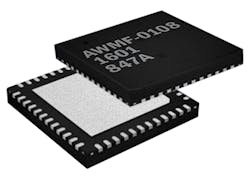
The AWMF-0108 is a highly integrated half-duplex transmit-receive silicon IC in a commercial 48-pin QFN-style surface mount plastic package with dimensions of 6 mm × 6 mm × 0.9 mm (Fig. 2). It easily fits within the typical 5.3-mm lattice spacing at 28 GHz. The IC is controlled though a 5-wire serial-to-parallel interface (SPI) bus and has ESD protection on all pins. The IC operates from a 1.8-volt supply with 0.54 watts consumption in receive mode and 0.92 watt in transmit mode.
Anokiwave offers design and evaluation kits to customers for early access to the technology. The kits include boards with the Ka-band IC, USB-SPI Interface module with drivers, and all required cables. Pilot production deliveries were available in June with full production quantities available in Q4 of 2016.
While the AWMF-0108 targets 5G cellular equipment, Anokiwave offers similar products for X-band active electronically scanned array (AESA) radar, as well as K and Ka-band satellites.
Engineers should welcome the AWMF-0108 as it provides a fast time to market design process that will surely improve competitiveness in the 5G equipment market.
This file type includes high resolution graphics and schematics when applicable.
About the Author

Lou Frenzel
Technical Contributing Editor
Lou Frenzel is a Contributing Technology Editor for Electronic Design Magazine where he writes articles and the blog Communique and other online material on the wireless, networking, and communications sectors. Lou interviews executives and engineers, attends conferences, and researches multiple areas. Lou has been writing in some capacity for ED since 2000.
Lou has 25+ years experience in the electronics industry as an engineer and manager. He has held VP level positions with Heathkit, McGraw Hill, and has 9 years of college teaching experience. Lou holds a bachelor’s degree from the University of Houston and a master’s degree from the University of Maryland. He is author of 28 books on computer and electronic subjects and lives in Bulverde, TX with his wife Joan. His website is www.loufrenzel.com.


