In today’s automotive industry, the number of electronic components built into vehicles is growing rapidly as electrically powered parts replace more mechanical parts and as driver assistance programs become more common. This shift is pressuring automakers and suppliers to find effective ways to protect electronic components against harsh contaminants and ensure reliable performance for the entire lifetime of the vehicle
Related Articles
- Dongles Watch Your Driving
- Ford To Expand Electrification Engineering Team By 50%
- Consumer Perception Inhibits Electric Vehicle Adoption
Electronic components such as compressors, pumps, motors, control units, and sensors in vehicles are exposed to rapid temperature fluctuations. For example, electronic components heat up when the vehicle is in operation. Then they cool down very quickly when they come into contact with cold spray from the road or at the car wash.
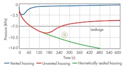
These temperature fluctuations can create a significant vacuum inside the housing. As a result, the housing seals can be compromised, allowing dirt particles and liquids to enter and corrode the components—eventually causing them to fail, which increases warranty issues and repair costs.
This file type includes high resolution graphics and schematics when applicable.
A major challenge for electric vehicles is the thermal management of high-performance electronics and batteries because they need to operate in a certain temperature range to achieve optimum performance. These components can get very hot when the vehicle is running, so fluids are frequently used to keep them cool. This causes significant temperature differentials inside the components, allowing condensation to form at the coldest point in the housing, which can lead to corrosion or cause a short circuit.
It is even more difficult to equalize temperature and pressure inside large batteries due to the size of the housing. For instance, driving a vehicle out of a warm garage into the cold weather can produce an interior vacuum that exerts a negative pressure of 500 kilograms per square meter. Lightweight housings are barely able to withstand that kind of pressure. Even minor temperature fluctuations can put enough pressure on a housing to cause deformation.
The easiest way to equalize pressure is to drill a hole in the housing to allow air to flow freely in and out. However, this allows liquid and particulates to enter the housing easily and compromise the electronics, causing them to fail.
Engineers have various ways to try to increase the reliability of sealed enclosures. Some engineers use a technique called potting to create a perfectly sealed system around the component by eliminating free space inside the housing. However, this makes the component significantly heavier, adding weight to the vehicle, and it cannot be reopened and repaired if the electronics fail.
Another way is to hermetically seal the housing so pressure cannot compromise the seals. The drawback of this system, though, is that the housing must be able to withstand the sealing process, which results in a more expensive, heavier component that cannot be reopened for maintenance or repair. The most common solution has been to install more rugged O-rings or gaskets in a more durable housing, while increasing the number of bolts to maintain a more durable seal.
These techniques do not guarantee that sensitive electronics will be protected long-term against harsh environments (e.g., dust, dirt, water, and automotive fluids) because they do not address the root cause of the failures—pressure differentials.
Venting To Improve Reliability And Durability
Incorporating a vent into a housing can reduce pressure differentials that compromise the component’s integrity. In an unvented housing, as little as 7 kilopascals (kPa) of pressure can cause seals to fail after several temperature cycles. Vented housings equalize pressure and prevent seal leakage (Fig. 1). These vents are constructed with a breathable membrane that equalizes the pressure inside the housing while preventing the ingress of liquids and dirt particles.
Gore uses expanded polytetrafluoroethylene (ePTFE) as the membrane in its automotive venting products because of its unique microstructure. The ePTFE is specially engineered to create very fine pores in which nodes are interconnected by fibrils (Fig. 2).
This material is extremely hydrophobic (water-resistant) thanks to its low surface tension, which means that water droplets on the surface are unable to penetrate the membrane structure. The membrane is also oleophobic (oil-resistant). Expanded PTFE’s oil-repelling properties are particularly important for automotive applications, because it is very likely that the electronic components will come into contact with motor oil, cleaning agents, or other automotive fluids.
In addition, ePTFE withstands temperatures ranging from –150°C to 240°C. Until recently, electronic housings were designed to withstand temperatures up to 125°C. However, the trend toward smaller, high-performance engines and electric car technology has pushed this threshold to temperatures above 150°C.
Airflow And Water Entry Pressure
Airflow and water entry pressure are two fundamental characteristics that determine a membrane’s performance. Airflow describes how much air can pass through the membrane in a given period at a given differential pressure (i.e., how long it would take to equalize a pressure differential inside a sealed component). Water entry pressure (WEP) is the minimum hydrostatic pressure that the membrane must be able to withstand before it leaks.
Factors such as the pore size of the membrane influence both parameters, so the venting supplier must determine the ideal combination of airflow and water entry pressure for an individual application. The trend toward increasingly compact electronic components means that vents must also be smaller. This in turn requires greater airflow per membrane surface area, resulting in a lower water entry pressure.
Testing To Ensure Durable Performance
In its global testing facilities, Gore verifies that its products meet the real-world challenges that they will encounter on the road to ensure the reliability of the venting solution and extend the component’s service life. The specific tests depend upon the electronic component and the types of challenges it will face. For example, the challenges for a sensor inside the passenger compartment are different from those encountered by a wiper motor. Some of the more common tests include ingress protection, chemical resistance, and temperature resistance.
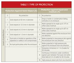
Typically, a completed system is tested according to the International Electrotechnical Commission (IEC) protocol IEC 60529 to determine its protection level against solid objects and liquids. Defined by two digits (IPXY), the ingress protection rating varies depending on the type of testing done. The first digit (X) indicates the protection rating against ingress of solid foreign objects. The second digit (Y) indicates the level of protection against ingress of liquids (Table 1).
For example, IPX9k shows how well a vented housing remains watertight when exposed to steam jets. The IPX9k test is carried out in a testing chamber in which the vented housing is exposed to a steam jet from a distance of 100 to 150 mm at angles of 0, 30, 60, and 90 degrees. The water rate is kept between 14 and 16 liters per minute (l/min), water pressure is maintained between 8000 and 10,000 kPa, and temperature is constant at 80°C.
Gore also follows ISO 16750-5 to test its vents’ ability to withstand chemicals and liquids commonly encountered in the automotive environment (Table 2). Tests are performed following one of two protocols: the vent is exposed to the liquid for 24 hours at room temperature (21 to 23°C), or it is heated in an oven for 96 hours at 100°C. Airflow and water entry pressure are measured before and after the test. To pass the test, both water entry pressure (WEP) and airflow must remain within Gore’s aggressive specification of 80 kPa, which exceeds the requirements of most automotive standards.
Also, Gore follows ISO 16750-4 protocols to test its vents’ ability to withstand extreme temperatures. In the temperature resistance test, the vent is exposed to a maximum temperature of up to 150°C for 2000 hours or to a minimum temperature of –40°C for 1000 hours.
In the ice dunk test, the vent is placed in a sealed housing and heated in an oven at a temperature between 80°C and 120°C for 40 to 60 minutes. The housing is then rapidly cooled to between 0°C and 4°C by placing it in iced water containing 5% sodium chloride, simulating the salt water that electronic housings are likely to encounter during the winter. This procedure is repeated 10 to 20 times, with venting properties measured before and after the test.
Venting For Different Applications
Types of electronic components are vast, comprising electronic control units (ECUs), motors, sensors, special latches, radar systems, key fobs, and more. Choosing the right vent to suit a unique application and its requirements is vitally important. Variables that can affect this decision include size, type, and thickness of housing; vent location; and installation method.
Gore works closely with its customers to evaluate the unique challenges of an application and recommend the best venting solution. Its application engineers also partner with its customers’ production teams to determine the best integration method, whether using manual, automated, or welded options.
Adhesive vents are appropriate for manual or automated installation. They are coated with a high-performance adhesive that adheres strongly to various kinds of metal and plastic. The long-lasting adhesive can withstand harsh conditions. These vents suit vehicle components such as automotive lamps because they reduce condensation by allowing moisture vapor to escape from the component while blocking entry of dust, dirt and liquid contaminants. For electronic components, pressure equalization is also critical. Combining these benefits with their low profile and easy installation have made adhesive vents a viable option for applications such as under-the-hood ECUs as well as hybrid and electric vehicle batteries.
Snap-fit vents can withstand the most challenging environmental conditions and are easy to install. Manufactured by integrating the membrane directly into the vent as part of the plastic injection molding process, they can be attached by simply snapping them into place in an opening in the housing. This process protects the membrane from mechanical loads without having to integrate expensive and complex protective walls into the housing. Furthermore, integrating the vent does not call for special machines or qualified experts. The vent is simply inserted in the housing via the “plug-and-play” method.
All-membrane cut-part vents provide a long-lasting, reliable solution for plastic housings that are exposed to high temperatures and strong chemicals. Available in different materials and sizes to suit the specific requirements of an application, they are attached using ultrasonic welding. At the weld seam, a small section of the housing material melts and flows into the porous structure of the membrane, guaranteeing that the joint is sealed and solid. This process does not compromise the membrane because ePTFE’s melting point is much higher than the welding temperature. The welding process can be complex, and it requires specialized tools. Also, walls have to be integrated into the housing to protect the vent from steam jets and mechanical loads. Gore’s engineers work closely with customers to help design the integration process for these applications.
Robert Lavertu is a product specialist with W.L. Gore & Associates Inc. He is responsible for the current sales and growth of Gore Automotive products in the North and South American markets. He has an MBA from the University of Maryland, Robert H. Smith School of Business, and a master’s degree in engineering from McGill University, Montreal, Canada.


