Thermal Simulation Boosts Reliability and Shortens Time-To-Market in Power Electronics System Designs
The drive for better efficiency in the power electronics industry has generated enormous gains in the last few years. The design of power semiconductors has improved, silicon carbide (SiC) and gallium nitride (GaN) process technologies have matured, and efficiency levels of 98% to 99% have been achieved in many power-conversion and switching products. However, it would be quite wrong to assume that thermal-management challenges have disappeared. They have not.
To start with, the stated efficiency figures are nearly always “best case.” Many power systems are operated under conditions that don’t reflect the idealized ones in the data sheet. For example, they may be run significantly below maximum load for much of the time—data-center power supplies are one example of where this is often the case. At these lower loads, efficiency usually declines, sometimes substantially. Power systems may also be operated with lower than optimal input voltages, or in extreme environments where ambient temperatures do not accord with those in the published data. An electrical control system in a Trans-Mongolian Railway train crossing the Gobi Desert faces very testing thermal conditions, for example. In short, many factors can contribute to real-world efficiency, and hence real-world thermal conditions, being different from those indicated in product specifications. Even if 98% efficiency is achieved, 2% of 2 kW is still 40W of heat that has to go somewhere.
As in many other electronic products, aluminum electrolytic capacitors—used for energy storage and filteringare often the life-limiting components in power systems. As a rule of thumb, these electrochemical devices, in which a wet electrolyte is continuously absorbed to reform the aluminum oxide dielectric layer, have their operating lives halved with every 10° C rise in temperature.
Clearly, there is not only a need to dissipate excess heat from power electronics units, but to do so in a way that minimizes temperature increases around the most vulnerable components. It’s important to consider thermal management of both the system as a whole and of its critical component parts.
This file type includes high resolution graphics and schematics when applicable.
Rules of Thumb
Experienced power electronics designers may employ a number of rules of thumb to progress their projects, but the process is iterative and time-inefficient. Thermal-design errors, where they’re detected, are corrected “on-the-fly” and every change adds time and expense to the project.
This approach, which is really just a combination of experience and guesswork, is usually fraught with inaccuracies. Knowing this, designers then over-engineer their systems to accommodate possible errors. They overrate components, use larger heatsinks or even liquid cooling, and generally end up making everything larger and more expensive than it needs be. In some instances a fan may be introduced when it’s not needed. Adding this electromechanical device significantly reduces the system’s Mean Time Between Failure (MTBF), a measure of expected operating life. Even with over-engineering, hidden problems can remain, resulting in poor reliability in the field, product recalls, and warranty claims.
This approach contrasts sharply with the use of accurate thermal simulation throughout the design process. Simulation empowers engineers to avoid over-engineering and to design smaller, lower-cost products that work better and last longer. Design time is reduced, resulting in more cost savings, and time-to-market is minimized, so revenues from new product introductions can be realized earlier.
Using Thermal Simulation
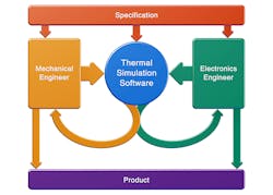
By using thermal simulation early in the design flow, the scale and number of changes needed to accommodate thermal factors is greatly reduced. Electronics, mechanical, and thermal engineers should co-operate so that the impacts of design changes on thermal performance are fully appreciated. Figure 1 describes the thermal design process.
To start with, a concept model showing electronic components as lumped blocks of heat will determine if the power electronics assembly can be created within the constraints of its broad specification. At this stage, the designer just needs to know total power dissipation of the assembly, its shape and size, and the type of heatsink that will be used.
After preliminary product design, accurate thermal modeling needs details of components and where they’re to be located on the printed circuit board, information on the estimated dissipation of the most significant heat-generating devices, and dimensioned outlines of the product enclosure. Simulation accuracy is directly related to the accuracy of the input data.
The simulation plots predicted temperatures that highlight where components may exceed their maximum ratings and the results guide PCB designers and mechanical engineers toward changes that may be beneficial to the thermal performance of the system as a whole. As the design evolves, the process is repeated.
Before going to the expense of creating a prototype, a final design simulation is run. Accuracy again depends on the input data, which should now include:
- Component thermal models, where manufacturers make them available.
- 3D CAD models of the system enclosure or housing. These can be imported into the simulation tool in a variety of industry-standard formats.
- Information about the characteristics of the materials used in the housing.
- PCB designs from EDA software. These can be imported using industry-standard formats such as IDF or Gerber.
- Details of copper traces within the layers of printed circuit boards.
- Updated data on the expected power dissipation of components within the fixture, derived from engineering calculations.
Simulation accuracy is verified by taking temperature measurements taken around and within the prototype. The accuracy of temperature sensors and thermometers needs to be considered when evaluating these results.
Evolving Tools
Thermal simulation tools for electronics design are based on computational fluid dynamics (CFD). Some can be too complex for non-specialists to use but, as with many types of software, they have become more intuitive to use in recent times, despite significant growth in their computational power and functionality.
Thermal simulation is nothing new. Mentor Graphics’ FloTHERM has been around for 25 years, for example. However, newer tools—such as 6SigmaET from Future Facilities—are rapidly earning a reputation for being incredibly easy to use in the hands of non-experts. Crucially, they do so without compromising accuracy or utility in the hands of experienced users.
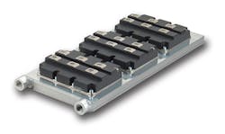
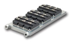
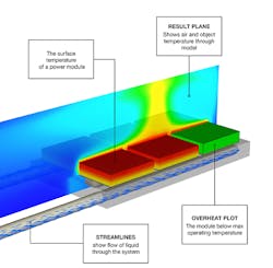
Release 9 of 6SigmaET was announced in October 2014 and it brings additional enhancements in usability and functionality, which further reduces design time and improves simulation accuracy. Figure 2 is a typical IGBT power module and Fig. 3 shows its thermal simulation results using 6SigmaET.
The simulation process uses component or system models represented as a mesh of grid cells. The cells are created from intelligent modeling objects, CAD models, and PCB layout data. A suitable grid—the quality and resolution of which determines simulation accuracy—can be generated in one of several ways. Engineers often need to then alter the grid resolution manually to focus on thermally significant parts of the design. This is a complex and time-consuming process that is now automated in 6SigmaET Release 9. Other features of the tool that make it easier to use include a drag-and-drop object panel and a user interface with context-sensitive ribbons that highlight the key actions for each task. This helps users quickly find the commands needed to create and analyze a model. Simulation speed, even for components and systems with complex geometries, has been improved to the extent that some simulations that previously might have taken hours can now be run in minutes.
About the Author
Tom Gregory
Product Manager
Tom Gregory is a Product Manager at Future Facilities Ltd. He has been working at the company for five years, and is responsible for marketing and supporting customers on the 6SigmaET side of the business.
Founded in 2004, Future Facilities Ltd. is a global company that provides thermal simulation software and consultancy for the electronics and data-center industries. Driven by a team of the world’s leading thermal simulation engineers and scientists, Future Facilities launched its tool for the electronics design market, 6SigmaET, in 2009.


