New-Look Position-Encoder Interfaces Enhance Motor Control
Download this article in .PDF format
Position encoders are sensors that, when used in industrial settings, produce critical motor information such as speed and position. The encoder delivers data for display or data that may serve as feedback in a motor-control system. Such information is supplied to a host microcontroller for processing according to the application. The link between the two is vital to system performance.
A number of different interfaces have been developed for encoders over the years. But implementing such an interface continues to challenge designers seeking cost-effective, precision, and safety features. However, the solutions outlined here attempt to overcome that hurdle by meeting those requirements.
Position-Encoder Fundamentals
Rotary encoders come in two basic flavors: incremental and absolute. Incremental encoders deliver a square-wave pulse output that can be used to indicate shaft speed. Most incremental encoders develop two square waves that are 90 degrees apart. These signals make it possible to determine the direction of rotation. In addition, a marker or index pulse is usually generated once per revolution to provide a reference point. Position can be determined by counting pulses between marker pulses.
Absolute encoders produce a parallel binary-code output that indicates an exact position in one shaft revolution. The use of the Gray binary code minimizes the errors in determining position. Absolute encoders may also develop a clock square wave and sine and cosine analog waves. The sin/cos signals provide a way to determine position more accurately.
Rotary encoders generate signals in different ways, including mechanical, magnetic, capacitive and optical methods. The optical encoder is the most common, as it produces the more precise data. It consists of a glass disk covered with a pattern of darkened and opaque areas representing the data to be output. An assembly of LEDs shines light on the pattern as it rotates. A group of photodiodes or phototransistors detect the light when it passes through, producing pulses representing the position code. The parallel binary codes developed indicate an absolute position in the rotation. These parallel signals are converted to serial format for output to the motor controller.
Absolute-Encoder Interfaces
A number of serial interfaces are available for absolute encoders. Most are proprietary to specific encoder manufacturers. Several popular types have emerged (including non-proprietary types), such as BiSS, EnDat, HIPERFACE, and SSI:
• BiSS: The Bidirectional Synchronous Serial (BiSS) interface was developed by IC-Haus of Germany. The interface defines a point-to-point connection from the encoder to the controller. Six lines are contained in a shielded cable, with one differential pair for the clock signal and another differential pair for the encoder serial data.
Data is transferred synchronously with the clock signal. The clock rate is determined by the cable length, which can to from 10 to 1000 meters. Maximum clock frequency is 10 Mb/s at 10 meters. Cable-length delay compensation is available.
The BiSS interface, which complies with the TIA/EIA RS-422 standard, has two additional wires that supply dc to the encoder. It’s hardware-compatible with the SSI interface described below.
• EnDat: The Encoder Data protocol is proprietary to Heidenhain of Germany. It defines a point-to-point connection with eight wires. One differential pair is for data and another pair for the clock; the other four wires are used for encoder power. Data transmission is synchronous with the clock, with clock rate dependent on cable length. Maximum rate is 16 Mb/s, while a typical rate at 100 meters is 8 Mb/s. It leverages the TIA/EIA RS-485 interface standard.
• HIPERFACE: HIPERFACE DSL (Digital Servo Link) was developed by Max Stegmann GmbH of Germany and SICK of the U.S. The point-to-point serial interface uses the TIA/EIA RS-485 standard. However, the protocol also supports a bus connection of multiple encoders.
The interface employs an eight-wire shielded twisted-pair cable up to 150 meters long. One differential pair is used for data and two pairs carry analog sine/cosine signals generated by the encoder. The sin/cos signals, digitized by 12-bit ADCs, are used to provide higher-resolution position measurement. Two additional lines supply power to the encoder.
Data transmission is asynchronous. In its standard version, the interface maintains a data rate of 38.4 kbaud. Another version of HIPERFACE can transmit at 9.375 Mbaud up to 100 meters.
A key feature of this interface is that it can carry feedback signals in the same cable, eliminating a separate cable. This is done by superimposing the feedback data signals on the dc supply wires.
• SSI: Perhaps the oldest original encoder interface is the Synchronous Serial Interface developed in Europe—it precedes all of the interfaces described above. SSI uses a six-wire cable with one pair of data, one pair for the clock, and a third pair for dc power. Data rate can be up to 1.5 Mb/s. Some SSI encoders supply sin/cos signals over another two-pair.
Implementing an Interface
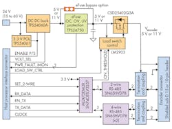
As a designer, you can build your own interface with an available IC of your choosing. However, a faster and simpler way is to use one of the interface reference designs from Texas Instruments. One such reference design is the TIDA-00179, which is a universal interface that can be used with any of the four standard interfaces summarized earlier.
Figure 1 shows the content of the design. The design is EMC-compliant and supports a dc input of 15 to 60 V (24 V typical). The built-in power components are designed to supply a regulated 5.25 or 11 V to the encoder. Overvoltage, undervoltage, overcurrent, and short-circuit protections are provided. RS-485 transceivers handle the data transmissions to and from the encoder. The design supports cable lengths up to 100 meters.
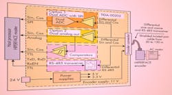
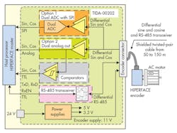
Another available reference is the TIDA-00202 for HIPERFACE encoders. Like the TIDA-0179, it provides the encoder power components that deliver 11 V from a nominal 24-V input. Also included is the RS-485 transceiver for data. The remaining circuits handle the analog sin/cos signals.
One path buffers the analog signals, and another squares them up into TTL-compatible signals. A third path digitizes the signal in dual 12-bit ADCs and supplies their outputs to an SPI interface to the controller. The design supports cable lengths from 50 to 150 meters. A variation of this design is the TIDA-00176 reference design, which is the interface for sin/cos-only encoders.
