Model-Based Systems Engineering Helps with Rugged Systems Design
What you’ll learn:
- How model-based systems engineering (MBSE) has improved system design.
- Thermal design and MBE come together.
When considering systems-level design, it’s important to understand the criticality of the system infrastructure, meaning all of the underlying hardware required to make the system work. Add in ruggedness and reliability requirements and it only increases the importance of the system infrastructure.
Systems design in general is being revolutionized by model-based systems engineering (MBSE), which is a big part of a broader move to Digital Engineering and Transformation that's sweeping industries worldwide.
In particular, defense systems suppliers continue to see more requirements from customers for MBSE to be performed for systems design. MBSE is now frequently replacing document-based systems engineering, with the promise of fewer defects, less rework needed later in the system development phase, and faster overall schedules.
Model-Based Systems Engineering Has Streamlined System Design
MBSE, a subset of model-based engineering (MBE), can and should integrate with other MBE outputs, such as thermal engineering/design, signal-integrity (SI) engineering/design, and mechanical engineering/design, which today tend to be performed in isolated silos.
MBSE enables a holistic MBE design approach that delivers powerful benefits—faster design cycles, fewer failures in test because you’ve created models and performed digital simulations, doing virtual testing in the computer—so that any issues can be discovered and fixed before a physical prototype is developed and tested. That process leads to higher-quality designs and more innovation, because “what-if” analyses can be performed faster and more easily.
In the real world, though, it’s very difficult to do MBE. There’s no free lunch. Successful MBE demands the following:
- State-of-the-art tools
- Highly skilled engineers and designers
- Years/decades of experience running the necessary tools
Engineers doing MBE especially need significant experience in correlating between modeling & simulation and validation & verification (V&V) test results, because the real world, unfortunately, has a habit of not behaving exactly like the model.
Accuracy is extremely important for effective modeling and simulation. Simply put: Garbage in/Garbage out. You can’t just turn the tools on and run them, you need skilled people to input good data into the tools to optimize their use and results. One example is material properties that are accurate in relation to the environments in which they will be used.
Take SI data as a specific example. Printed-circuit-board (PCB) laminate materials suppliers will provide certain properties such as dielectric constant and loss factor, which are very important for SI.
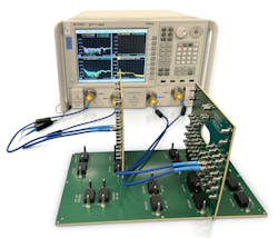
This data will be based on the suppliers’ own testing, but those properties are going to vary over temperature and humidity and as a result of manufacturing processes. If those variances aren’t considered, the data can turn out to be 2X or 50% inaccurate. You need to fully understand the data that you’re entering into the model so that you get accurate output information (see figure).
Mechanical design is one of the oldest MBE disciplines. For over five decades now, the use of computer-aided design (CAD) has become commonplace. CAD creates a 3D model of the design; for example, the system chassis and its components (backplane, I/O boards, plug-in modules, power supplies, etc.). In addition, engineering analyses such as stress, shock, and vibration can be performed on the CAD model.
CAD forms the basis of computer-aided manufacturing (CAM). Once you create a CAD model of a chassis, for instance, the model can be sent to a machine shop so that a physical prototype can be machined out of aluminum based on the 3D model. Similarly, for the PCB (backplane), electrical and mechanical CAD design can be sent to a PCB shop where the data is used to create the PCB itself.
Today, the CAD information fed into the CAM process is based on the supplier’s design. Although there’s often a design-for-manufacturability (DFM) feedback loop, it may turn out that the proposed design still isn’t fully optimized, and it ends up being beyond the cost and complexity limits allowed by the project after the machine shop accepts the CAD files.
In the years to come, artificial intelligence (AI) and machine learning (ML) hold out the promise to enable a more bilateral workflow that will optimize size, weight, power and cost (SWaP-C), as well as other considerations. It will soon be possible to use design tools that embed DFM knowledge that can be integrated with CAD tools. Therefore, automatically, as a design is being created, inputs derived from a knowledge base can feed the DFM knowledge back into the CAD process to guide the designer to a more optimal approach.
Thermal Design and MBE
Thermal design used to be an “over the wall” discipline. In other words, electronic designers would first do their design, such as selecting the components and laying them out on a board, and they would also start working with the software engineers to create the required functionality. Afterward, when a prototype would need to be produced, they’d hand the project over to the mechanical engineers to figure out how to cool the module.
At that point, if the various disciplines haven’t worked together, to influence, for example, where the components should be placed to optimize cooling, the mechanical engineer might come back with the bad news that the proposed design will be 10 or 15°C over the maximum junction temperature and the design will fail.
In that scenario, the electronic designer must go back to the drawing board and shift the location of the various components around, resulting in rework churn and longer development cycle time. To avoid this wasted effort, it’s best to get the thermal engineers involved early, starting with a quick thermal analysis.
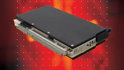
With today’s high-performance modules and systems, such as Curtiss-Wright’s 100-GbE speed Fabric100 product suite, it’s critical to perform thermal MBE early and properly. What is properly? To begin with, the mechanical engineers need to take that hardware design and model it physically and accurately, because they’re going to interface such things as conduction cold plates and air flow through heat exchangers to that electronic design to effectively cool it.
For each of the module’s high-power components, it’s essential to understand the accurate heat loads (i.e., both power dissipation levels and densities), which can vary depending on what kind of functionality is going to be run. And it’s not just the overall power-dissipation levels that come into play. It’s also critical to get into the nitty-gritty details of the power density across the silicon chips on the components. Power densities can drive which cooling approach should be taken.
Accurate material properties data is as important for thermal design as it is for SI. For example, thermal conductivity data from thermal-interface material suppliers can actually be an order of magnitude off when tested in an independent lab. Take nothing for granted: trust but verify.
Another aspect that’s become very important due to the increased use of liquid-flow-through (LFT) and air-flow-through (AFT) cooling approaches for high-power modules and systems is the availability of accurate cooling and coolant characterization (e.g., air flow, liquid flow using computational fluid dynamics [CFD] modeling & simulation). Otherwise you can expect real struggles during the prototyping and implementation phases. Examples of leading CFD modeling/simulation tools are Ansys Icepak, Cadence Celsius, and Siemens Flotherm.
SI has risen in importance as modules and systems evolve to support 100-GbE speeds. At higher speeds, many more factors in the design must be considered, such as tolerances on differential-pair geometries and impedances. Understanding the geometries and material properties is critical.
SI is a highly specialized discipline that requires subject-matter experts and tools that are both expensive and rare. As a leading supplier of rugged modules and systems, Curtiss-Wright has invested in the tools and the talent to produce high-performance, high-reliability Fabric100 solutions.
Similar to thermal design processes, SI also requires accurate modeling, simulation, and test. Experience with MBE increases confidence and familiarity with the tools and discipline, delivering improved results over time. Again, as it is with thermal design, good SI design requires accuracy when it comes to material properties, such as the Worse Case High Temperature (WCHT) properties of the PCB laminate. Examples of leading tools for SI design include Ansys HFSS and COMSOL Multiphysics for 3D electromagnetic modeling and simulation.
MBE for rugged-system infrastructure design involves modeling and simulation using state-of-the-art tools, processes, and knowledge. Correlation with test results is essential to ensure accuracy. A successful MBE effort will result in shorter development cycles, fewer failures and rework, more innovation, and ultimately higher-quality products. Customers will be pleased with the results.
About the Author
Ivan Straznicky
CTO and a Technical Fellow, Curtiss-Wright Defense Systems
His responsibilities include leading and supporting advanced technology innovation and initiatives in a collaborative and efficient manner. Subject matter areas include thermal management, high speed signal integrity, reliability, hardware and mechanical design, and electronics manufacturing. Ivan has over 35 years experience in the defense & aerospace electronics industry in manufacturing, engineering, technology and management.

