A Power Module or Discrete Design for Your DC/DC Conversion? How to Choose
This file type includes high resolution graphics and schematics when applicable.
Let’s face it: Some lucky folks don’t have to worry too much about power conversion. Just plug the board into the backplane, and “Abracadabra!” As if by magic, a range of exquisitely-regulated power rails with zero noise and insanely fast load response are available to respond to the slightest need.
The BLDC needs 36V at 20 amps? Not a problem. Low noise ±3.8V for that custom transducer? Done.
In your dreams, perhaps. In the real world, though, engineers aren’t quite so lucky. Many systems make use of a single-bus voltage, perhaps 24V, and rely on point-of-load (POL) DC/DC converters to generate local power.
There are two main options available for this purpose: a discrete design and an integrated power module. Each one has its strong points and weak points.
Which is best for your design? Let’s take closer look at some of the factors to be considered.
Comparison of Modules vs. Discrete Designs
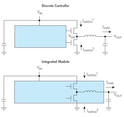
1. A discrete design and an integrated power module are two options for power supply POL designs. Each one has its pros and cons. (Source: Texas Instruments)
Figure 1 shows the main blocks in a discrete controller solution and a power module. A power module integrates the controller, the inductor, and many of the passive components into a single package. Compared to a discrete approach, a module requires less design and debug time and has a smaller footprint. The integrated design has a lower part count, which saves manufacturing and inventory costs. It also tends to have lower output noise and emissions because the traces between internal components are much shorter than would be possible in a discrete layout.
On the other hand, a power module integrates many features and fixes design parameters, preventing them from being optimized for a particular application.
The discrete design allows for greater design flexibility and has a lower BOM cost. It takes up more board space, but its larger footprint can give better thermal performance because it distributes the heat over a larger area.
How do they stack up?
Let’s compare two solutions: a discrete design based around the LM3152 and a modular design using the LMZ14203. Both components are part of TI’s SIMPLE SWITCHER family. In each case, the design has VIN = 24V, VOUT = 3.3V, and can deliver a maximum output current of 3A.
Online tools are available to help with switching power supply design and layout. TI’s WEBENCH Power Designer, for example, includes footprints for multiple power components: Designers can quickly design a power supply, create a PCB layout, and export the results to a CAD program.
Schematic and Cost
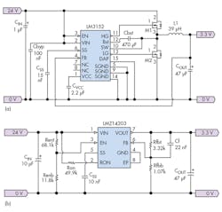
Figure 2 shows the schematics of the discrete and module designs.
2. Components needed for a 24V-to-3.3V design using (a) the LM3152; and (b) the LMZ14203. (Source: Texas Instruments)
Both designs used the WEBENCH tool to develop the schematic and select the external components. Each design used 10 components in total, but there were significant cost differences. The modular design required only $0.69 of resistors and capacitors, but had an estimated total BOM cost of $10.19; the discrete design needed $1.69 of external components including resistors, capacitors, an inductor, and two FETs, but its estimated total BOM cost was only $4.14.
Using the online design tool simplified the design process considerably compared to a traditional approach; even so, the discrete circuit required some part changes and design simulation.
PCB Layout
Laying out the printed circuit board (PCB) for a switching regulator for optimal performance requires minimizing the size and length of the high-current, high-frequency nodes, as well as managing the routes taken by the return currents.
Putting together a power supply that “works” is a task within reach of many layout engineers. Ensuring the supply is robust and operates with minimal noise emissions is an art that needs careful thought and knowledge of the circuit operation.
Traditionally, design engineers have relied on application notes, copying of reference layouts, and their own judgment to create power supply board layouts. Unwanted noise and thermal problems can result, and multiple design iterations may be needed.
The modular design combines many of the key components in an optimized layout, so it’s less prone to mistakes. In addition, many power module packages allow a layout designer to place an unbroken top-layer copper plane underneath the package. This enables maximum heat conduction between the die and the copper to keep the junction temperatures as low as possible.
Using WEBENCH to compare the PCB area needed for a discrete and modular design yields the table shown in Fig. 3 for a single-side layout. The component PCB footprint is shown in units of mm2 and includes a 1 mm per-side margin to allow for clearance. The table also adds an additional 50% packing factor to include traces and open spaces.
3. A WEBENCH comparison of the PCB area needed for a discrete and modular design. (Source: Texas Instruments)
Noise Performance
Both discrete and modular switching power regulators generate noise that can interfere with the operation of other circuits—particularly low-voltage analog systems. In this article, we’ll confine ourselves to a discussion of the output voltage noise generated by the two designs.
Although it’s not necessarily always the lowest-noise choice, a modular design has a built-in advantage since the circuit traces connecting the regulator components are much shorter than in a discrete design.
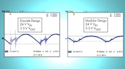
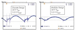
4. A comparison of output noise ripple illustrates the superior performance of the modular design. (Source: Texas Instruments)
Figure 4 compares the output noise performance of the discrete and modular designs. The LMZ14203 stacks a shielded inductor on top of the controller in a three-dimensional package to minimize trace length and inductance.
The scope plots are taken from the LM3152-3.3 and LMZ14203 evaluation boards. The discrete design shows more high-frequency noise spikes due to the additional parasitic inductance and capacitance of the longer traces on the PCB. A 1-in.-long trace adds about 20nH parasitic inductance to the circuit.
These spikes can also cause higher levels of conducted and radiated noise, which may cause the design to fail a noise emissions test.
For both designs, it is possible to reduce the voltage ripple by lowering the total capacitor equivalent series resistance (ESR). This can be achieved by changing to a low-ESR capacitor such as tantalum or OS-CON, or adding more capacitance in parallel.
In addition to ESR, inductor size, input voltage, switching frequency, and other factors can affect output voltage ripple. A discrete design has more options here, but also more room for error.
The Advantages of DC-DC Power Modules
Certain applications lend themselves to a modular design. An extremely short design cycle might not allow sufficient time to design, validate, and qualify a discrete solution; it’s also recommended in cases where the needed power supply design expertise is not readily available.
Severely space-constrained applications that require the smallest solution size are another good fit for a modular solution.
Are Power Modules Always Better?
Although power modules have many desirable features if you’re looking for ease of use or small size, they’re not always the best solution.
A discrete design has an advantage in a high-volume application where lowest cost is a top priority. Many power modules reduce footprint by stacking components in a three-dimensional package; this increases height and may disqualify them in some applications.
Sometimes the issues are design-related. For example, many designers working with field-programmable gate arrays (FPGAs) are not power supply experts, so a power module might seem the obvious choice.
But caution is needed. An FPGA generates load transients of many different frequencies; it typically requires power supply decoupling capacitors of hundreds or even thousands of µF to maintain regulation and reduce ripple.
As we’ve seen, power modules achieve simplicity by integrating many of the passive components to reduce the design effort, but there are drawbacks. For example, integrating the control-loop compensation components constrains the range over which the design is stable. An internally-compensated power module may not be stable when faced with a large FPGA capacitance. For more information, this application note discusses optimizing the stability of regulators that use TI’s DCS-Control topology.
Some applications may require a tightly-specified minimum and maximum start-up time. Although the LMZ14203 features adjustable soft-start (SS), in many modules the SS time is fixed and set internally to a compromise value. To meet a specific startup time requirement, a discrete design may be a better choice if a suitable power module with programmable SS (typically using an external capacitor) isn’t available.
Conclusion
We’ve talked about discrete designs and power modules, but a range of other options is available, featuring different levels of integration. For example, some devices integrate the drive FETs but leave the selection of the inductor up to the designer. And, of course, at higher power levels, complete modules are available that require no external components—essentially, a complete standalone power supply with a price to match.
For many low- to medium-volume applications, though, power conversion is more of a necessary evil than a point of differentiation. In such cases, the power module is the preferred choice to get your project up and running with minimum time and effort.


