New Discovery Could Lead to Commercial Production of Permanent Magnet Motors
A number of readers questioned the veracity of the technology presented in this article. To address their concerns, we did a follow-up, which can be found here.
Permanent magnets are an integral part of many motors that take advantage of advances in obtaining powerful and stable magnetic materials.
Today, rare earth magnets containing lanthanide elements such as neodymium and samarium carry large magnetic moments. For example, a neodymium (NdFeB) magnet comprised of neodymium, iron and boron and measuring only 10.16cm X 10.16cm X 5.08cm can have a Brmax of 14,800, a surface field Gauss of 4,933, a pull force of 557 kg, and is stable at 176ºF. Unless overheated or physically damaged, the magnet will lose less than 1% of its strength over 10 years.
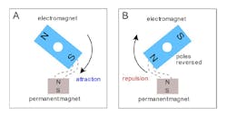
To see the impact of permanent magnets we have to look at a typical electric motor. As an external power source passes through the rotor field, it serves as an electromagnet that is attracted to the permanent magnet causing the motor to rotate (Fig. 1A). For continued rotation, the electromagnet allows the rotor field to reverse the polarity of its magnetic field (Fig. 1B) producing repulsion. The repulsive force between the poles repels the electromagnet along its path of motion. If polarity of the rotor is not reversed, the attractive force that pulled the electromagnet toward the permanent magnet will prevent the electromagnet from escaping and cause it to return and rest opposite the permanent magnet.
An electric motor that uses permanent magnets does not have field windings that serve as electromagnets on the stator frame. Instead, the permanent magnets on the stator frame provide the magnetic fields that interact with the rotor field to produce torque. This eliminates the need to power the stator, thereby reducing electrical energy consumption.
Electric motors, with or without the use of permanent magnets, produce rotation from a repeated sequence of attraction followed by repulsion, which requires reversing polarity. Many attempts have been made to construct a motor using only permanent magnets to generate the magnetic fields for both the stator and the rotor, but they did not succeed.
Such a motor would be powered entirely by the intrinsic magnetic fields generated by permanent magnets. The discovery presented here allows permanent magnets to attract and repel in sequence, producing continued motion like an electric motor and without reversing polarity or the use of an external source of energy.
Most of us have handled permanent magnets and experienced the attractive and repulsive forces that occur between them. It is easy to imagine having the magnets do work for us. For example, the attractive force between two sufficiently strong permanent magnets can move an object as the magnets pull themselves together. However, to have the magnets repeat this work, they must be pulled apart.
The amount of work or mechanical energy required to pull the magnets apart is similar to the amount of mechanical energy the magnets generated when they pulled themselves together. Accordingly, permanent magnets are unable to work continuously on their own without an external source of mechanical energy to repeatedly pull them apart.
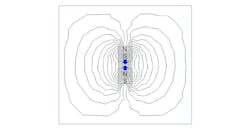
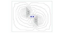
Fig. 2 illustrates typical field lines between opposite poles of two permanent magnets that generate the commonlyexperienced attractive force exerted in the polar (vertical) plane. The attractive force generated by sufficiently strong magnets can pull the magnets together over a distance until they come to rest in contact with one another. The attractive force between opposite poles can also pull the magnets together along an equatorial (horizontal) plane until they come to rest opposite one another. Fig. 3 illustrates the field lines responsible for this horizontal attraction.
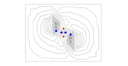
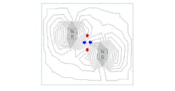
It is common for attract and repel forces to exist between two magnets with opposite poles facing as illustrated in Fig. 4. However, the repulsive force in the polar plane is usually very weak compared to the attractive force in the same plane causing the resultant force to be attraction. We have created a unique condition in which the fields of two permanent magnets with opposite poles facing, generate a resultant attraction force between them in the equatorial plane and a resultant repulsion force in the polar plane, simultaneously.
Fig. 5 illustrates the field lines responsible for the simultaneous equatorial attract (blue arrows) and polar repel (red arrows) forces occurring between a pair of permanent magnets. The unusual resultant repulsion in the polar plane is a result of the shape of the magnets and their positions and is generated between like poles even though the magnets have their opposite poles facing one another.
The resultant attractive force exerted in the equatorial plane can be used to pull the magnets together horizontally. The resultant repulsive force exerted in the polar plane can, in turn, be used to push the magnets apart vertically without reversing polarity or the use of other energy. Thus, two permanent magnets are made to pull themselves together with an attractive force and then push themselves apart unaided by an external force or other energy.
Normally, an external force must be applied to separate two permanent magnets that have pulled themselves together with their attractive force. Until now, we have not observed two permanent magnets attract and repel themselves in sequence, unaided. This sequence of attraction followed by repulsion is like the attract-repel sequence that occurs in an electric motor between a permanent magnet and an electromagnet.
Attract-Repel Demo
We constructed an apparatus to demonstrate the simultaneous resultant attraction in the equatorial plane and the resultant repulsion in the polar plane between two permanent magnets with opposite poles facing one another. To reduce friction during motion, the permanent magnets were attached to carts with eight wheels. Four permanent magnets were positioned on each cart.
The magnets were made of neodymium (NdFeB), grade 52, and measured 5.08 cm long, 2.54 cm wide and 1.27 cm thick. They were magnetized through their 1.27 cm thickness. Each magnet has a Brmax of 14,800 Gauss and pull force of 41.28 kg. To minimize magnetic interference, the carts and rails were made of aluminum alloy and the screws and nuts were made of brass.
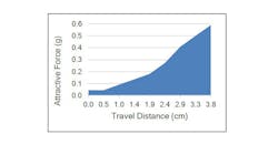
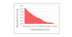
The resultant attractive and repulsive forces were measured using an IMADA model DS2-110 digital force gauge. Resultant forces applied to the carts were measured at 3.18 mm intervals along the horizontal and vertical paths of motion. Measurements were made of the resultant attractive force in the equatorial plane responsible for horizontal motion, as shown in Fig. 6. Measurements were also made of the resultant repulsive force in the polar plane responsible for vertical motion (Fig. 7).
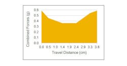
The combined force values from the attractive force in the equatorial plane and repulsive force in the polar plane is presented in Fig. 8. A surplus of mechanical energy is available from total force (mechanical energy) available during the attraction and repulsion phases. This surplus of energy can be used to do work such as drive an electric generator. The data provided here are intended only to illustrate the phenomenon and do not represent the optimal conditions for maximum energy output.
Motor Design Considerations
Repeating the sequence of attraction and repulsion described here requires that the magnets return to their starting positions. However, the short distance traveled by the magnets described here leaves them within the attractive and repulsive fields responsible for their initial motion. Therefore, returning the magnets to their starting positions would be opposed by these residual attractive and repulsive forces, respectively.
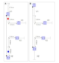
A considerable amount of the mechanical energy would have to be spent to overcome these forces when returning the magnets. These opposing residual forces and the expenditure of energy to overcome them can be greatly reduced by extending the distance traveled by magnets H and V. For example (Fig. 9), if magnet V were made to travel 15.24 cm vertically instead of 6.35 cm, magnet H could then move back horizontally to its starting position without encountering significant opposition from the attractive force in the polar plane.
With extended travel distances, the resultant attractive force in the equatorial plane initially will be too weak to pull magnet H horizontally. Fig. 9 illustrates how pairs of magnets can be linked together to tow one another along a portion of their travel. The repulsive force between magnets V1 and H1 is sufficiently strong for magnet V1 to tow magnet H2 in closer to magnet V2 where the attractive forces are stronger. In turn, the attractive force between magnets V2 and H2 can tow magnet V1 further away from magnet H1. Motion generated by two pairs of magnets linked together are illustrated in Fig. 9.
This connection of magnet pairs in different phases of the attraction and repulsion sequence is like the arrangement of pistons in a combustion engine in which the combustion stroke of one piston drives the exhaust stroke of another piston. Another similarity exists in that both magnets and pistons travel along linear paths as they provide mechanical energy.
Mechanical energy can be conserved by making the magnets work at both ends of their travel. In this manner, energy is not wasted returning the magnets to their original positions to repeat the cycle. Connecting four pairs of magnets completes the cycle, allowing for continued motion driven entirely by permanent magnets.
It is noted here that the stator and rotor in a conventional electric motor requires several pairs of magnets to achieve continued motion. The attraction and repulsion sequence between one stator magnet and the electromagnet (rotor) cannot produce sufficient inertia to turn the rotor one full rotation and repeat the cycle. Likewise, the method described here requires the use of multiple pairs of permanent magnets to extend travel distances and complete a cycle.
Commercial Application
The method described here illustrates how permanent magnets alone can be used to produce continuous motion and provide a surplus of mechanical energy that can be used for other purposes such as driving an electric generator.
For many reasons, electromagnetic energy from permanent magnets is a highly practical, clean, and abundant source of energy. Electromagnetic force has been calculated to be 39 orders of magnitude stronger than gravitational force and its intrinsic source is abundant. The amount of energy required to create permanent magnets is insignificant compared to the amount of electromagnetic energy intrinsically available from them after they are magnetized. Iron, the most common ferromagnetic substance, is the second most abundant metal on Earth.
The powerful magnets containing neodymium and samarium are not required to generate a practical amount of net mechanical energy using the method described here. Other weaker permanent magnets can be used. The stability (coercivity) and strength (magnetic moment) of permanent magnets today are extremely high. The magnitude of the electromagnetic forces exerted between magnet pairs to generate mechanical energy as described here is below the coercivity value of the magnets. Therefore, the magnets will remain stable under normal operating conditions.
The Future
A permanent magnet motor has been constructed and it is undergoing testing. Also, a patent has been applied for the motor and its details will not be available until the patent is granted.
One feature still to be determined is the best way to turn the motor on and off. With a typical electric motor you merely use a switch to turn power on to activate the motor and then turn the power off to stop the motor. You can’t do that with a motor consisting of permanent magnets. Several methods of interruption are under consideration. One approach is to use an electromagnet to provide braking. The electromagnet would only be powered during the braking period and would be off when the motor is running.
References
1. G. E. Uhlenbeck, S. Goudsmit, Spinning electrons and the structure of spectra. Nature. 117, 264-265 (1926).
2. H. Foley, P. Kusch, On the intrinsic moment of the electron. Physical Review 73, 412-412 (1948).
3. R. Feynman, Electromagnetism. The Feynman lectures on physics. 2, Chapter 1 (1962).
4. M. E. Peskin, D. V. Schroeder, An Introduction to Quantum Field Theory (Westview Press, New York, 1995).
5. R. Penrose, The Emperor's New Mind: Concerning Computers, Minds, and the Laws of Physics (Oxford University Press, Oxford, 1989).
6. W. L. Eric, Magnetism: An Introductory Survey (Courier Dover Publications, New York, 1963).
About the Author

Sam Davis Blog
Editor-In-Chief - Power Electronics
Sam Davis was the editor-in-chief of Power Electronics Technology magazine and website that is now part of Electronic Design. He has 18 years experience in electronic engineering design and management, six years in public relations and 25 years as a trade press editor. He holds a BSEE from Case-Western Reserve University, and did graduate work at the same school and UCLA. Sam was the editor for PCIM, the predecessor to Power Electronics Technology, from 1984 to 2004. His engineering experience includes circuit and system design for Litton Systems, Bunker-Ramo, Rocketdyne, and Clevite Corporation.. Design tasks included analog circuits, display systems, power supplies, underwater ordnance systems, and test systems. He also served as a program manager for a Litton Systems Navy program.
Sam is the author of Computer Data Displays, a book published by Prentice-Hall in the U.S. and Japan in 1969. He is also a recipient of the Jesse Neal Award for trade press editorial excellence, and has one patent for naval ship construction that simplifies electronic system integration.

