The ISOW784x family of high-performance, four-channel reinforced digital isolators from Texas Instruments employs an integrated isolation barrier to provide high efficiency and isolated power. The ISOW784x supports an input voltage range of 3V to 5.5V and provides a regulated 5V or 3.3V, 0.65W output.
This family of devices is suitable for applications that have limited board space and require more integration. They are also suitable for very-high voltage applications, where power transformers meeting the required isolation specifications are bulky and expensive.
To be useful, an integrated power and signal isolation solution must offer high efficiency, high power delivery, and low emissions while offering high isolation performance. Isolation is a means of preventing dc and unwanted ac between two parts of a system while still enabling signal and power transfer between those two parts. Isolation is used in a variety of applications to:
- Protect operators by isolating low-voltage from high-voltage circuits; industrial standards require reinforced isolation at 2x the basic level needed for proper equipment operation.
- Improve noise immunity.
- Handle ground potential differences between communicating subsystems.
- Prevent high-frequency noise from propagating.
- Protect sensitive circuitry from high-voltage surges and spikes.
One of several family versions, the ISOW7841 provides a four-channel high-performance digital isolator that operates up to 100 Mbps, with a typical propagation delay of 13 ns. The integrated dc/dc switch-mode converter uses advanced circuit techniques to reduce power losses and boost efficiency, supporting 130 mA of load current with 5 V input and 75 mA of load current with 3.3 V input. Integrated closed-loop feedback provides excellent line and load regulation. Special emissions-reduction techniques aid in meeting emissions standards.
The key to its signal isolation capabilities is a capacitive circuit using silicon-dioxide (SiO2), for a dielectric that is integrated on the same chip as other circuitry. This second generation of capacitor-based integrated reinforced isolation technology provides protective pass through of high-voltage, high-frequency signaling. Products made with this process offer reliability, electrical protection and reinforced isolation equivalent to two times the basic isolation in a single package.
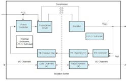
Figure 1 shows a functional block diagram of the ISOW784x.The integrated dc-dc converter uses switched mode operation and proprietary circuit techniques to reduce power losses and boost efficiency. Specialized control mechanisms, clocking schemes, and the use of a high-Q on-chip transformer provide high efficiency and low radiated emissions. The integrated transformer uses thin film polymer as its insulation barrier.
The VCC supply applied to the primary power controller switches the power stage connected to the integrated transformer. Then, power is transferred to the transformer’s secondary, rectified and regulated to either 3.3 V or 5 V, depending on the IC’s SEL pin setting. A dedicated isolation channel consisting of FB Controllers and FB Channel (Tx and Rx) monitors output voltage (VISO) and feeds back information to the transformer’s primary via the Power Controller. This feedback is used to adjust the duty cycle of the primary switching stage. The fast feedback control loop of the power converter ensures low overshoots and undershoots during load transients. Undervoltage lockout (UVLO) with hysteresis is integrated on the VCC and VISO supplies, which ensures robust system performance under noisy conditions. Integrated soft-start ensures controlled inrush current and avoids output overshoot during power-up.
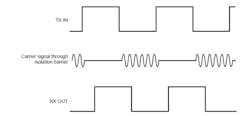
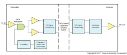
The integrated signal-isolation channels transmit the digital data across the SiO2 isolation barrier using on-off keying (OOK) modulation (Fig. 2). After conditioning the signal, the receiver demodulates the signal and produces the output through a buffer stage. The signal-isolation channels incorporate advanced circuit techniques to maximize the CMTI performance and minimize the radiated emissions from the high frequency carrier and IO buffer switching. Common‐Mode Transient Immunity (CMTI) describes an isolator’s ability to tolerate high-slew-rate voltage transients between its two grounds without corrupting signals passing through it. Figure 3 shows a functional block diagram of a typical ISOW784x signal isolation channel.
EMC Considerations
Emissions reduction schemes for the internal oscillator and advanced internal layout minimize radiated emissions at the system level. This is necessary because applications in many harsh industrial environments are sensitive to electrostatic discharge (ESD), electrical fast transient (EFT), surge and electromagnetic emissions. International standards such as IEC 61000-4-x and CISPR 22 specify electromagnetic disturbances. The ISOW784x family incorporates many chip-level design improvements for overall system robustness, including:
- ESD protection for inputs, outputs, and inter-chip bond pads.
- Low-resistance connectivity of ESD cells to supply and ground pins.
- High voltage isolation capacitors with enhanced performance to provide better tolerance of ESD, EFT and surge events.
- Large-value on-chip decoupling capacitors for bypassing undesirable high energy signals through a low impedance path.
- Guard rings for PMOS and NMOS devices, isolating them from each other to avoid triggering their parasitic SCRs.
- Differential internal operation that ensures reduced common mode currents across the isolation barrier.
The ISOW784x family has built-in UVLO (undervoltage lockout) on the VCC and VISO supplies with positive-going and negative-going thresholds and hysteresis. When the VCC voltage crosses the positive-going UVLO threshold during power-up, the dc-dc converter initializes and the power converter duty cycle increases in a controlled manner. This soft-start limits primary peak currents drawn from VCC and VISO, avoiding overshoots. Outputs of the isolated data channels are in an indeterminate state until the VCC or VISO voltage crosses the positive-going UVLO threshold. When the UVLO positive-going threshold is crossed on the secondary side VISO pin, the feedback data channel starts producing feedback to the primary controller. The regulation loop takes over and the isolated data channels go to the normal state defined by the respective input channels or their default states. Designers should consider a sufficient time margin (typically 10 ms with a 10 μF load) to allow this power up sequence before using valid data channels.
Thermal Overload Protection
This family is protected against output overload and short circuit. Output voltage starts dropping when the power converter is not able to deliver the current demanded during overload conditions. For a VISO short-circuit to ground, the duty cycle of the converter is limited to help protect against any damage.
Thermal protection prevents the device from being damaged during isolated output overload and short-circuit conditions. Under these conditions, the device temperature starts to increase. When the temperature goes above 180°C, thermal shutdown activates and the primary controller turns off, which removes the energy supplied to the VISO load and causes the device to cool off. When the junction temperature goes below 150°C, the device starts to function normally again. If an overload or output short-circuit condition prevails, this protection cycle is repeated. Device junction temperatures should always be prevented from reaching such high values.
Typical Application
Figure 4 shows the typical schematic for SPI isolation. Here an ISOW7841 isolates the MCU output from an Analog-to-Digital Converter (ADC). This isolates the MCU and ADC grounds to avoid any ground loops that are detrimental to system operation.
More Isolation Barriers
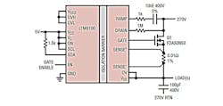
Another device that uses a galvanic isolation barrier is the LTM9100 µModule (micromodule) from Linear Technology. It uses the barrier to separate logic inputs from its Power Switch Controller. This device differs from TI’s ISOW784x. Instead of providing I/O isolation, it accepts logic inputs that can turn high voltage power sources on and off using an external power MOSFET or IGBT. Here, the isolation barrier protects its low voltage logic inputs from neighboring high voltage Power Switch Controller. This internal isolated Power Switch Controller and external power MOSFET/IGBT can turn1000Vdc on and off.
The key to the LTM9100’s power protection is its internal 5kVRMS galvanic isolation barrier that separates the digital input interface from the Power Switch Controller that drives an external N-channel MOSFET or IGBT switch (Fig. 5). The micromodule has an I2C interface that provides access to isolated digital measurements of load current, bus voltage and temperature, which allows power and energy monitoring of the high voltage bus.
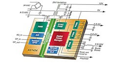
Akros Silicon, which has been acquired by Kinetic Technologies, might have been the first to employ an integrated isolation barrier. An article in the October 2009 issue of Power Electronics Technology described Akros’ integrated 2kV digital isolation technology that employs an isolation barrier. Akros calls its isolation barrier GreenEdge, which has gone through several iterations and now includes the AS1454/51/44/34/31/24/22 that are quad/dual/single-output digital Power SoCs for 9.5-72VDC and 24VAC isolated power applications. Figure 6 shows the AS1454.
Synchronous converters with digital analog loop and digital timing control are integrated with digital isolation as part of an advanced power system architecture for high-efficiency and cost-effective designs. Selectable spread-spectrum clocking on all PWMs reduces the power supply spectral noise for superior EMC performance. Bi-directional Isolated GPIO and isolated ADC ease system level design in many industrial and medical applications.
With two externally-programmable high-current capable outputs (Vout1 and Vout4), and two internal Buck Regulators (Vout2 and Vout3, with 1.25A option in AS1424/34 and 2A option in AS1444/54), the device family provides a scalable platform solution for sub-50W range applications. An I2C-compatible management interface provides advanced power control and diagnostics capability only in the AS1431/34 and AS1451/54. Hardware-programmable device operation is also available supported on all seven devices. The AS1451 and AS1431 provides a single isolated output, whereas the AS1822454 provides dual quad isolated outputs.
About the Author

Sam Davis
Sam Davis was the editor-in-chief of Power Electronics Technology magazine and website that is now part of Electronic Design. He has 18 years experience in electronic engineering design and management, six years in public relations and 25 years as a trade press editor. He holds a BSEE from Case-Western Reserve University, and did graduate work at the same school and UCLA. Sam was the editor for PCIM, the predecessor to Power Electronics Technology, from 1984 to 2004. His engineering experience includes circuit and system design for Litton Systems, Bunker-Ramo, Rocketdyne, and Clevite Corporation.. Design tasks included analog circuits, display systems, power supplies, underwater ordnance systems, and test systems. He also served as a program manager for a Litton Systems Navy program.
Sam is the author of Computer Data Displays, a book published by Prentice-Hall in the U.S. and Japan in 1969. He is also a recipient of the Jesse Neal Award for trade press editorial excellence, and has one patent for naval ship construction that simplifies electronic system integration.
You can also check out his Power Electronics blog.

