The August print issue of EE-Evaluation Engineering includes a special report on power electronics test. In preparation for that article, we asked test equipment vendors to provide information on their products and strategies. Ken Johnson, director of marketing and product architect, and Jeff Krauss, applications engineer, both at Teledyne LeCroy, provided extensive feedback. In the Q&A below, they elaborate on points raised in the print article.
Q. Teledyne LeCroy offers the MDA800 motor drive analyzer. What is unique about this product?
A. Power analyzer instruments perform only one function. They can be useful as a “golden reference” power measurement device, but they are limited to steady-state analysis and provide simple black-box insight. A 4-channel and/or 8-bit oscilloscope serves basic embedded control debug and validation but comes up short on inputs for complex drive system and control-loop analysis. They also lack the vertical resolution to precisely measure power and efficiency values. The MDA has none of the above limitations.
As with a power analyzer instrument, the MDA provides a user-configurable table for display of a selection of power (real, apparent, or reactive), power factor, phase angle, efficiency, voltage, current, or motor mechanical parameters. Numeric values displayed are mean values from a statistical data set calculated on a “per-cycle” basis using a user-defined synchronization source signal. This display corresponds to what is normally provided by a dedicated power analyzer instrument. Unlike a power analyzer, the MDA has capability to analyze dynamic events. All per-cycle values are calculated, and the variation of these values over time can be displayed as a per-cycle “synthesized” waveform. Additionally, Zoom+Gate can be used to select an area of interest in a long (several second) acquisition and gate the Numeric (mean) table values and the per-cycle Waveforms to just this area of interest. This is especially helpful as most failures occur during dynamic, and not static (steady-state) conditions.
The HDO8000 series and MDA800 series are available in three bandwidths of 350 MHz, 500 MHz, and 1 GHz. All models offer eight analog input channels, a sampling rate of 2.5 GS/s, and 50 Mpoints/channel of acquisition memory (250 Mpoints/channel optional). These models also features Teledyne LeCroy’s HD4096 High Definition 12-bit technology.
Q. At what stage of the design, development, and production process are these products used (for example, debug, validation, characterization, production, failure analysis)?
A. Oscilloscopes, especially 12-bit resolution oscilloscopes with high (1-GHz) bandwidth, are used in all aspects of design debug, validation, characterization, and failure analysis. These tools are used less often in production environments, but there are some who integrate these capabilities into production test equipment.
For debugging and validation of embedded motor controls the MDA800 motor drive analyzer provides static (steady-state) power tables like a power analyzer instrument, performs dynamic power analysis, and provides complete embedded control debug like a fully-functional oscilloscope. For motor speed and torque integration, the MDA provides torque and tachometer functions as well as analog/digital measurement of motor speed and position. It also performs mechanical power calculations.
In the area of IGBT and MOSFET power device testing, the PWR software option performs VDS and VGS voltage monitoring, ID (drain) current monitoring, and measurements of switching and conduction losses.
Q. What types of measurements are your instruments making (for example, I-V or other electrical parameters or thermal or other parameters?
A. For power semiconductor device testing (a single IGBT or FET) our instruments measure
- switching and conduction loss;
- safe operating area of switching device;
- Rds(on), or the resistance of a conducting device; and
- dv/dt and di/dt, or the rate of change of voltage (dv/dt) or current (di/dt) through a switching device.
They also perform
- control-loop response analysis;
- line power consumption analysis; and
- line harmonics pre-compliance testing to EN 61000-3-2.
For power conversion system testing (multiple IGBTs or FETs in a system that performs a higher level function) our instruments perform static steady-state three-phase analysis (measuring various voltage, current, real power, apparent power, reactive power, phase angle, power factor, etc. parameters) and dynamic three-phase analysis (measuring various voltage, current, real power, apparent power, reactive power, phase angle, and power factor parameters).
They also measure per-cycle synthesized waveforms as well as torque, speed, and angle (electrical and mechanical). The perform mechanical power calculations and provide analog/digital signal acquisition, serial data acquisition and trigger/decode, and gate-drive (PWM) monitoring.
Q. Are there any other unique features about your solutions you would like to emphasize?
A. Eight input channels plus 12-bit resolution make the Motor Drive Analyzer and HDO8000 series oscilloscopes ideal for high-power and three-phase power electronics analysis. No other eight-channel instrument on the market aimed at power electronics test offers a full oscilloscope’s feature set, including MSO capability, serial trigger/decode capability, and standard oscilloscope tool kit and probes.
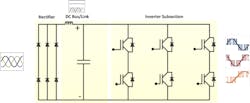
The VFD’s output is a PWM, three-phase signal which, when applied to the motor winding, induces a near-sinusoidal current to flow in the winding. The characteristics and quality of the voltage output signal, and the resultant current in the motor winding, are related to the PWM control methodology and the amount of inductance in the motor winding. Control of the width of the PWM signal results in more or less voltage applied to the winding, which in turn results in more or less current draw in the motor.
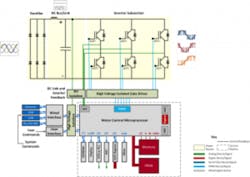
VFD inverters are built with various power semiconductors, including power MOSFETs, IGBTs, HV IGBTs, and/or IGCTs (insulated gate commutated thyristors). A common configuration for a two-level inverter uses a “six-switch” system with the switches being three pairs of power semiconductors in the inverter’s output. Each of the three pairs of switches controls the positive and negative voltage modulation activity of one of the motor’s three phases.
For such applications, an absolute minimum of six analog input channels is required (three voltage and three current). Having more than six channels would permit simultaneous viewing of signals from control lines, serial data, and/or sensors. The core applications, though, are looking at the three-phase output (three voltages/three currents/other signals) and looking at the power semiconductor devices (VGS and VDS on as many devices as possible simultaneously to ensure proper switching operation). Thus, the more channels, the better.
Figure 2 shows the kind of complexity presented by a typical inverter block diagram. Not only are there the three pairs of power transistors that make eight analog input channels so necessary, but there is also the matter of an MCU, interfaces to numerous sensors, and any number of serial protocols to debug. This is where the HDO8000’s optional 16 digital channels come in.
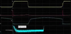
The MDA and HDO 8000 series incorporates Teledyne LeCroy’s HD4096 High Definition technology, using a 12-bit data acquisition front end that delivers 16 times more horizontal resolution than 8-bit instruments. As a result, users see signals in much detail; with 8-bit instruments, fine detail is often lost in quantization noise.
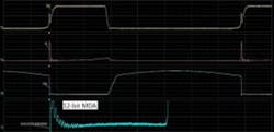
For example, say you’re looking at a MOSFET’s VDS saturation voltage in a switched-mode power supply application. An 8-bit oscilloscope displays a fuzzy saturation voltage trace with little or no detail (Figure 3a), while an MDA shows a clean trace with plenty of detail (Figure 3b).
Finally, bandwidths range from 350 MHz to 1 GHz. MDA bandwidth requirements are typically related to the complexity of the control system (and the processor speed used in the control system). Complex Vector FOC controls may utilize processors running at 700 MHz or higher, which requires a 1 GHz MDA, whereas lower complexity controls require less bandwidth.
A Webinar on the MDA provides more information.
About the Author

Rick Nelson
Contributing Editor
Rick is currently Contributing Technical Editor. He was Executive Editor for EE in 2011-2018. Previously he served on several publications, including EDN and Vision Systems Design, and has received awards for signed editorials from the American Society of Business Publication Editors. He began as a design engineer at General Electric and Litton Industries and earned a BSEE degree from Penn State.
