This article was originally published as a Design Brief in the October 13, 2005 print edition of Electronic Design magazine
Solenoids and relays used in electronic control applications consume lots of power. The current required for activation is typically three to 10 times higher than the minimum needed to hold the relay or solenoid in the ON position. Thus, reducing the driver's operating current after the solenoid or relay is switched ON will save power and reduce thermal loading. The technique presented here substantially reduces power dissipation when the device is ON.
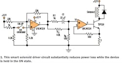
The circuit employs an op amp to generate a constant-current sink, which uses a power transistor that drives the solenoid (Fig. 1). The reference voltage for the current sink is shaped in such a way that within tens of milliseconds after the solenoid is switched ON, the current drops and is maintained at more than (by a suitable safety margin) the minimum needed to hold the solenoid in ON state.
The circuit was designed for a solenoid operated from a 12-V supply. The solenoid needs around 800 mA to switch on, but it requires less than 100 mA to remain ON. The ON command input signal connects the positive supply voltage at the noninverting input of the comparator formed by part of the LM324 (pin 3). After activation, the reference point (pin 10) for the current-sink portion of the circuit (formed by part of the LM324) is driven high by the comparator output (pin 1 of the LM324). This will drive the transistor (TIP120) into saturation as in the standard circuit.
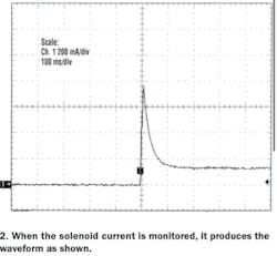
After a predefined time determined by the R1-C1 time constant, the reference point to the current sink settles to the final steady-state value determined by the RB/RA ratio and the current-sense resistor (1Ω). Thus, the circuit turns on the solenoid like a standard circuit (driving 760 mA into the solenoid) and later settles to the reduced operating-current mode (140 mA).
The waveform for the solenoid current monitored on the circuit is illustrated in Figure 2 . The reduced ON-state current in the solenoid cuts its power dissipation. Unlike a standard circuit, additional power dissipation will exist in the driver transistor and resistor at the emitter of the transistor. However, the total power dissipated in the circuit will be substantially lower.
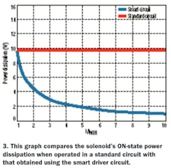
The power dissipated in the solenoid is reduced by the square of the current reduction (P = I2R), while the major part of the additional power dissipation in the driver transistor follows a linear relationship: P = VI. The calculated power dissipated in a standard circuit and the power dissipated in the smart circuit (including the power dissipation in the solenoid, the driver transistor, and current-sense resistor) is up to 10 times lower than the activation current for a solenoid operating from a 12-V supply and drawing 800 mA of current (Fig. 3).
This circuit can be easily adapted to drive relays or solenoids operated from other voltage levels. Considering the increased power dissipation in the driver transistor, a suitable heatsink should be used with it.


