Use Current Measurement As A Leading Indicator For System Thermal Management
System thermal management has become more critical as two trends work against each other in modern electronic systems: driving higher performance in smaller form factors. Historically, systems have managed this by measuring the system’s temperature. However, temperature typically is a lagging indicator. The increase in system temperature normally is a result of increased current flow. Measuring the current allows the system integrator to manage the thermals in their systems more efficiently and anticipate problems instead of reacting to potential issues.
This file type includes high resolution graphics and schematics when applicable.
System Thermal Management
System thermal performance management is critical in today’s electronic systems. As systems grow more powerful and in many cases smaller in size, managing the thermal profile to prevent system damage has become an ever-increasing challenge. Whether we consider the newest high-performance smartphone or a large industrial controller, it is important to keep the temperature within the recommended operating conditions to maximize performance and user experience.
Related Articles
- When Heat Is On, Thermal Characterization Keeps Things Cool
- Thermal-Management Design Banks On Advanced Materials/Adhesives
- Manage Your MCM's Thermal Issues
Many systems use thermistors or temperature sensors to monitor the temperature at key locations in the system. While this works fine, measuring the temperature means that we are monitoring a secondary or lagging indicator. Temperature increase is due to an increase of the system current flow. To stay ahead of any potential thermal problems, it is preferable to monitor a leading indicator rather than a lagging one. Since the temperature rise most likely is due to an increase in the system current, monitoring the current enables early detection. There are many reasons to measure the current for system monitoring and protection.
System Reliability
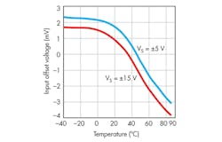
The amount of current flow in the system greatly impacts system reliability. An increase in current correspondingly increases the IC’s junction temperature. As the junction temperature increases, the performance (such as bandwidth, offset voltage, and gain accuracy) of the IC could be impacted (Fig. 1).
In an extreme case, junction temperatures can exceed the maximum operating conditions. This can permanently damage the IC and lead to system damage. Even if permanent damage is not a result, long-term exposure to elevated operating conditions can degrade IC performance, which can result in system reliability issues.
Characterizing the system to understand the current load profile can provide valuable insight into the areas of concern in the system. Enabling distributed-current monitoring instead of a single-system current also can allow issues to be identified earlier. Many newer digital power monitors have integrated an ALERT function. These ALERTs can free up the system management controller from having to continuously monitor each of the currents and only respond to areas of concern. Once an alert is triggered, the system management controller implements corrections immediately, if the threshold is set close to the danger point.
Conversely, setting the threshold at a lower, less dangerous level triggers the system management controller to start monitoring the current and make decisions based on the current level activity (continuously increasing, versus a spike). Whether it takes immediate action or responds based on current level trends, the system management controller can affect system operating conditions by such means as turning on cooling systems or slowing down clock speeds, all to reduce the current consumption.
Safety
Monitoring for safety is not just about preventing catastrophic failures, such as the system catching fire. The issues to avoid can range from preventing permanent harm to system components to burning the user.
As discussed, all components have maximum operating conditions. If left unchecked, increasing load current eventually causes the IC to exceed the absolute maximum junction temperature ratings. In the most severe case, the IC can ignite from the heat. This type of catastrophic failure is rare. But the consequences can be costly in terms of system damage and potentially could lead to bodily injury.
Monitoring the current can enable the management system to identify possible issues well before they become dangerous. It then can take preventive actions as discussed and, in the most adverse of conditions, simply shut down the system to reduce current flow to below dangerous levels.
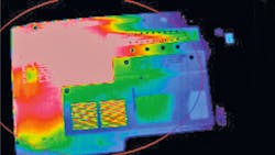
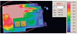
User safety has become a bigger concern with personal electronics. Many of us have felt the burn when we use our laptop computers sitting in our laps for extended periods. According to WebMD, temperatures as low as 109.4°F (43°C) can burn human skin.1 In the lab we measured a maximum temperature of 61.1°C on the bottom surface of a laptop plugged into the wall and running a PC performance test software utility (Fig. 2).
As smartphones and tablets continue to offer greater performance in ever-smaller form factors, there just isn’t any room to add a cooling system to help minimize a unit’s surface temperature. Characterizing the system to understand how the surface temperature is directly proportional to the load current again allows for managing the system to prevent the current from reaching dangerous levels.
System Performance
Here, we aren’t discussing chip-level performance degradation, as was covered above. Rather, this is about how monitoring load currents can help maximize system performance. To help explain this, let’s look at a central office scenario.
With the focus on greener systems, minimizing power consumption is critical. By monitoring the load current in large communication systems, power consumption and performance can be balanced. In a blade server, there are multiple communication cards. During off-peak hours, enabling only a single card minimizes system power consumption. But if you monitor the current being consumed by the communications processor, you can detect when the load (number of “users”) is increasing and bring additional cards on line. By monitoring the load current you can optimize the user access experience by bringing on the appropriate number of communication cards while minimizing the active power consumption.
Fault Protection
If a system has a fault such as a short to power or ground, serious system failures and damage are possible. Therefore, it is critical to detect faults as early as possible to prevent the damage. Clearly waiting for the corresponding increase in temperature related to the sudden increase in current that results from a short may be too late to prevent damage.
In the case of fault detection, actually knowing the current level most likely is not needed. Simply detecting when the current has exceeded a pre-defined threshold may be all that is required. In many systems this is accomplished by a fairly low-performance current detection amplifier, followed by a comparator that trips when the load current causes the voltage output to exceed the comparator’s threshold.
Many of the newer digital output current shunts, such as the INA230, have a built-in ALERT functionality. It allows for the current shunt monitor to act as a simple over-current detector, similar to the output of the two-stage approach of an amplifier and comparator. In either situation, this alert can immediately trip a fuse or relay (without the system management controller needing to process the current level) to remove the load from the supply voltage and prevent any additional damage to the system.
Summary
Monitoring the current in the system provides a leading indicator of potential issues. Whether the concern is system performance, system reliability, or basic safety concerns, knowing as early as possible of a potential issue can minimize system downtime or prevent even worse problems.
References
1. WebMD, Laptop Risk: Toasted Skin Syndrome, Oct. 4, 2010
2. Download this datasheet: www.ti.com/ina230-ca.
About the Author
Dan Harmon
Marketing Manager, Current and Power Measurement Product Line
Dan Harmon is the marketing manager for the Current and Power Measurement Product Line at Texas Instruments. In his 30-year career at TI, he has supported a wide variety of technologies and products including interface products, imaging analog front-ends (AFEs), and charge-coupled device (CCD) sensors. He also has served as TI’s USB-IF representative and TI’s USB 3.0 Promoter’s Group Chairman. Dan earned a BSEE from the University of Dayton and a MSEE from the University of Texas in Arlington. He can be reached at [email protected].


