Single 48V to 1V, 200A Converter Powers Microprocessors (Part 3)
Download this article in PDF format.
For Parts 1 and 2, click here and here.
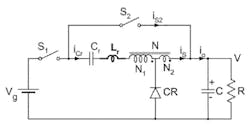
The Hybrid Switching converter operates from either 48V or 12V input to generate 1V, 200A output. It eliminates switching losses of all three MOSFET devices and the transformer leakage inductance losses to achieve over 99% efficiency. It’s the only converter that handles large and fast load current transients in a fraction of a single switching cycle—with one module and only three MOSFET switches!
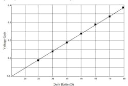
Obviously, the converter can be scaled up in current to 100A and 240W at 2.4V, as illustrated in Figure 11, provided the resistive losses are likewise reduced by use of appropriately scaled resistive losses of the components.
11. Linear voltage gain measurement.
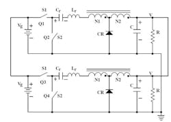
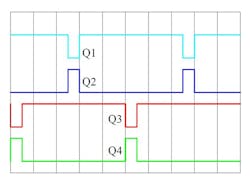
Only two identical converters operated in parallel but shifted in time for exactly half a switching period (Fig. 12) are sufficient to reduced output ripple voltage to an ultra-low value despite using 20 times less capacitance then needed in a single synchronous buck converter. Figures 12 and 13 show the circuit and its timing diagram, respectively.
12. Two identical converters operated in parallel.
13. Timing diagram showing paralleled converters shifted in time for half a switching period.
Note the simplicity of the practical implementation of two modules in parallel. Only one converter needs to be made; the second module is an identical converter, whose operation is shifted exactly by a half switching period. Hence, the control only needs to include a sync pin to implement this parallel connection.
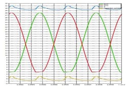
The current waveforms in Figure 14 show near complete cancellation of the ripple current and drastic reduction of the filtering capacitor needed on the output to achieve ultra-low ripple voltage.
14. Verification of near ripple-free current for 30A DC load and 0.5 rms ripple current at 200kHz. Red trace: module 1 output current; green trace: module 2 output current; blue trace: total output current DC+ AC ripple; orange trace: output capacitor ripple current.
In the previously simulated example for 48V to 2.4V, 100A converter output power of two modules would be 540W. Yet the filtering capacitors needed would have only a 2.4V rating and would use capacitors with a much lower value than a filtering capacitor needed for a single buck converter. Hence, both resonant capacitor Cr and the output capacitor C would be ultra-compact even at 500W.
Eliminating Transients
The Hybrid Switching converter is the first one with a unique property: The peak resonant current drawn from the source is directly proportional to the DC load current as given by Equation 6 (see Part 1). Therefore, the sudden change of the DC load current as experienced in microprocessors will eliminate voltage transients in less than half the switching period. This feature is inherent to both the Hybrid Switching converter as well as the Storageless Switching converter, in which both intervals have their own defined resonances.
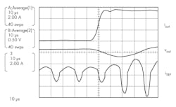
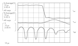
Experimental measurements recorded for a converter using Hybrid and Storageless Switching converters (Figs. 15 and 16, respectively) are both representative of the inherent fast transient performance with both methods.
15. Typical one-cycle transient in hybrid switching.
16. Typical one-cycle transient in storageless switching.
Experimental Verification
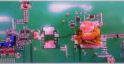
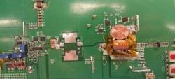
The early breadboard prototype (Fig. 17) demonstrates small-size magnetics (compared to a penny) even at a 100kHz switching frequency. The experimental waveforms also confirm the zero voltage switching (ZVS) of the two MOSFET transistors.
17. Small hybrid transformer at 100kHz switching frequency.
The size of magnetics is directly proportional to flux per output number of turns. For a 1-turn secondary, N2 = 1, and at 100kHz, we get 0.5V output.
Voltsec/N2 = 0.5V x 10µs = 5Vµs (14)
For the AC flux density of 0.25T, this translates into a core cross-section of only 20mm2. It’s identical to what a separate inductor in single buck converter would need. Here, there’s only one additional primary winding of 1 turn. Since both windings are foil windings, there’s actually minimal increase of the window area to implement a 1:1 turns ratio transformer.
There’s a reason for selecting 50 kHz as an upper limit. Below that frequency, there’s no requirement regarding radiated EMI noise, as this is deemed too low of a frequency band to interfere. ZVS of ideal switches and zero-current switches of the diode eliminate spike noise and conducted noise by definition anyway, so expensive filtering measures for conducted and radiated noise mitigation can be reduced significantly, or even eliminated entirely.
Obviously, current GaN and SiC device proponents would continue their hype that megahertz switching frequencies are needed to reduce the size of magnetics and hence justify the need for devices with high speed. Nothing is further from the truth, though, as they would work much better below 150kHz. In addition, they have to learn that conventional topologies not only abuse them with a 10X or higher overkill in frequency, but also with simulations 10X or more in their device voltage requirements, such as for a 48V to 1V direct buck with GaN devices. Brute force with both isn’t a solution, but rather a huge detriment for wider use of those otherwise excellent switching devices.
One might get the wrong impression that the application of the Hybrid Switching converter is limited to microprocessor drives due to its unique property of handling large and fast load transients. This isn’t the case—its ultra-high efficiency, small size, and low cost make it an ideal choice also for all automotive applications for direct 48V to 1V conversion, point-of-load applications, FPGA power supplies, and many other applications.
Conclusion
The key results are summarized here. All other present approaches have three fundamental drawbacks for 48V to 1V conversion:
- They use a two-stage conversion approach with an intermediate bus converter (IBC) for 48V to 12V conversion and separate 12V to 1V multiphase synchronous buck converters with up to 12 stages operating at a 5MHz switching frequency.
- They’re not able to provide fast transient response naturally in a single stage. Instead, they require a number of parallel stages (eight or more) at an ultra-high 5 MHz switching frequency.
- Their size, cost, and weight are an order of magnitude larger than that achievable by two identical Hybrid Switching modules.
Dual use for either 48V or 12V inputs
One additional advantage of the described solution for 48V to 1V conversion is that it could be directly utilized for 12V, 1V µP drives by simply adjusting the transformer turns ratio and using appropriate lower-voltage-rated switching devices. This will also allow for a smooth transition from the present 12V to 1V to new advanced 48V to 1V µP drives needed in the near future.
One attractive alternative for 12V to 1V, 100A for microprocessors is to eliminate magnetic cores entirely and provide the power supply on a chip using a PWM resonant converter (see “Step-Down dc-dc Converter Eliminates Ferrite Cores at 50kHz Enabling Power Supply on Chip with One-Cycle Transient”).
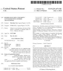
NOTE: This converter is protected by US Patent applied on March 28, 2011 and issued on January 6, 2016 as US 9,231,471 B2. Below is an illustration of the first page of the actual patent:
The companies interested to license the converter and partner with TESLAco in developing products are welcome to contact Dr. Slobodan Cuk at [email protected] or via Skype on slobodan.cuk.
Slobodan Ćuk came to the U.S. from Belgrade, Yugoslavia in February 1972 on a NASA sponsorship. NASA supported his Master’s thesis at the University of Santa Clara, Calif. Then he received his doctorate from CalTech in 1974. Afterward, he taught power electronics at CalTech for 25 years. He is the author of a four-volume book series on Power Electronics as well as many papers and articles on power electronics. In 1979, he established TESLAco to develop (among others) hybrid power modules for NASA’s ORION spacecraft, high-voltage converters for implantable heart defibrillators, the F22 power supply, and space station switching converters.
Latest Masterclass update and related articles and links:
POWER ELECTRONICS: 50 YEARS IN 4 DAYS! March 25-28, 2019 at UCI campus Register at teslaco.com/courses. Early registration with discount expires January 25, 2019!
Three Power Electronics Courses in One:
CLASSICAL: Topologies, Magnetics and Control (2 days)
NEW: Resonant Switching Methods &Topologies (2 days)
LIVE SIMULATIONS with .plecs and SIMPLIS (all 4 days)
Learn about obsoleting buck, boost, flyback and forward converters; power Supply on chip with no magnetics cores at 50kHz; direct 48V to 1V µP drive with fast transient at 100kHz; and transformer and inductors and BH loops on a scope.
Other key topics include:
• Topologies, Magnetics and Control
• State Space Average (SSA) Modeling
• Hybrid and Storageless Switching Methods
• Coupled-Inductors and Integrated Magnetics Methods
• Original Ćuk converters and the latest inventions
• Magnetic demonstrations using 1MHz B-H loop tester
• Live simulations of classical and new topologies
• Elimination of magnetic cores for inductors at 50kHz
• Buck, boost, flyback, and forward converter replacements
The course will take place during Spring break at UC Irvine and will be offered in the week following the APEC conference in Anaheim (20 minutes away).
To see highlights of the 1st Masterclass from September 25-27, 2018, check out these videos:
https://youtu.be/8Apc746RTS0
https://youtu.be/jxUjatOrHoo
https://youtu.be/AWb8NVIjE8M
https://youtu.be/JNtRhSrf16I
About the Author
Slobodan Cuk 1
Slobodan Ćuk is an author, inventor, business owner, electrical engineer, and professor of electrical engineering. The Ćuk switched-mode dc-dc converter is named for him. For over 20 years, until January 1, 2000, he was a full-time professor of electrical engineering at the California Institute of Technology (Caltech). In 1979, Slobodan founded TESLAco, which is currently located in Laguna Niguel, Calif. It had a charter to apply basic research results developed at Caltech to commercial, space, and military designs. This ultimately resulted in a family of hybrid Ćuk converters incorporated in the Orion spacecraft slated to land on Mars before 2030.
Other works produced at TESLAco include a multiple-output Ćuk converter incorporated in the F-22 Joint Strike Fighter plane; a heart defibrillator using a high-voltage step-up Ćuk converter, which was implanted in over 100,000 patients; and use of a similar converter by Ford Motor Company for HID lamps in their cars. More recently, the Ćuk-buck2 converter and PWM Resonant Ćuk converters have been patented and are available for license along with other patents. To date, over 50 patents have Ćuk's name on them. At the PCIM Europe 2011 conference, Leo Lorenz introduced Ćuk as a "father of power electronics." After five decades in the field, Cuk hopes to be remembered both as one of the founders of classical power electronics as well as a "father of modern power electronics."
