Download this article in PDF format.
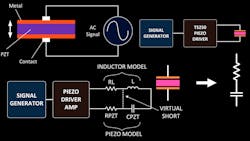
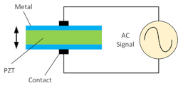
Jacques and Pierre Curie, French physics, discovered the piezoelectric effect in 1880. When some solid material is mechanically compressed or stressed, the material accumulates electrical charges on its surface and develops a voltage potential. This is the piezoelectric effect. The inverse piezoelectric effect is when the process occurs in reverse. When voltage potential is applied to certain ceramic materials, they expand and contract physically as shown in Figure 1.
1. An ac sinewave applied to a piezo device causes the material to expand and contract.
It’s been more than 100 years since the discovery, and during that time numerous scientific research efforts have led to the invention of many superior piezo materials. In turn, we’ve seen the creation of a wide range of practical piezoelectric devices.
Today, most piezo devices (sometimes referred to as PZT) use the inverse piezoelectric effect. Example of such devices include piezo motors, actuators, speakers/buzzers, ultrasound devices for imaging and levitation, high-power ultrasonic transducers for cleaning, etc. These PZT devices operate over a very wide range of voltages, frequency, and waveforms. Some only require dc voltages, while others need ac voltage waveforms such as sine and square. Certain devices require low voltage in the few tens of volts, while others need hundreds and even thousands of volts.
Driving PZT devices that require high voltage, oftentimes accompanied by high frequency and high capacitance, can be very challenging. This article shows how a series-resonant technique can handle the challenge by boosting the output voltage. But first let’s look at the non-resonant driving method, then compared to the resonant method.
Direct Drive (Non-Resonant)
The most convenient way to drive piezoelectric actuators and other devices is to connect them to the piezo driver (Fig. 2). A direct driving method offers direct control over voltage range and waveform shape (sine vs. square). Most of the time, piezo elements are driven this way. It’s the recommended method for driving piezo motors and elements if the PZT driver met the voltage and power requirements.
2. The TS250 piezoelectric driver amplifier directly drives a high-capacitance transducer.
A piezo amplifier driver is commonly used for direct driving of high-frequency and high-capacitance transducers such as actuators, buzzers, motors, etc. PZT transducers and motors are very capacitive in nature. If the frequency is high, their impedance is low due to their large capacitance. Because of low impedance, a fairly high-current piezo driver amplifier is required, especially at ultrasonic frequencies.
The PZT actuator current is formulated by Ohm’s law in Equation 1. Z is the piezo impedance. Rearrange Equation 1 to Equation 2. Substituting Z = 1/(2πf) into Equation 2 yields Equation 3. The current is directly proportional to voltage, frequency, and capacitance as indicated in Equation 3. The current symbol is I, the voltage symbol is V, C is the capacitance, and f is the frequency.Let’s use the following example: a piezoelectric actuator with 1-µF capacitance, operating at 18 kHz, which requires 40 V peak-to-peak and a peak current of 4.5 A (9 A p-p). Using direct drive, a high-current piezoelectric driver amplifier is needed. At higher frequencies, it often requires even more driving current.
Resonance Boosts Piezo-Driver Voltage
As long as the PZT driver can output the required voltage, current, and frequency, the direct-drive method (Fig. 2, again) is the most straightforward to work with. There are usage cases where the piezo actuator and other devices require higher driving voltage than the driver can supply. For example, a piezo amp driver’s maximum output is 80 V p-p, but the required voltage is in the hundreds or even the thousands and still must maintain high frequency.
It’s increasingly difficult and expensive to obtain high voltage and still achieve a high-frequency and high-current PZT driver amplifier. Fortunately, there’s simple solution to enable a lower-voltage piezoelectric amplifier to boost to higher voltages. A series-resonant technique can boost the driving voltage and become a high-voltage driver and generator. Voltage boosting can be accomplished by adding a series inductor (Fig. 3). The next three sections offer detailed explanations on how a series-resonance circuit can boost voltage for capacitive devices.
3. A series inductor is used to boost piezo transducer voltage. The red trace indicates a high-voltage connection.
Caution: With the high-voltage circuit presented in Figure 3 and the rest of the discussion, use high-voltage engineering techniques such as high-voltage wire plus connector. Avoid touching any part of the high-voltage components and connections.
Piezo Model and Series Resonant
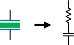
4. A simplified model of a piezoelectric transducer is shown.
Piezo devices such buzzers and actuators are mostly capacitive and can be designed as a capacitor with a series resistor (Fig. 4). The series resistance is normally small. With the piezo modeled as a series RC, Figure 3 becomes Figure 5. Note the resonant inductor also modeled with a small parasitic series resistance.
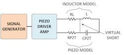
5. This circuit shows impedance cancellation and a virtual short circuit at resonant.
As shown in Figure 5, adding a resonant inductor forms a series LCR resonance circuit. Note the two parasitic resistors are connected in series and can be combined into one small resistance. In Figure 5, the LCR resonance circuit is driven by a high-frequency piezo driver. At resonant, the driver only “sees” those two parasitic resistances.
The resonant frequency for LC tank circuit is given in Equation 4. Rearrange Equation 4 to solve for the inductance value, which is calculated in Equation 5. To better understand how series resonance can boost the voltage, let’s understand impedance cancellation discussed below. To summarize, the resonance circuit is transforming an ordinary piezo amp into a high-voltage piezoelectric driver.Impedance Cancellation
Referring to Figures 3 and 5, the series inductor is acting as impedance cancellation device. At the resonance frequency, both the inductor and the PZT capacitor have the same impedance, but an opposite polarity. They are 180 degrees out of phase. These two impedances cancel each other out. Thus, the inductor is a device that cancels capacitor impedance.
Impedance cancellation is modeled as a virtual short circuit at resonance frequency. As shown in Figure 5, there’s a short circuit between the inductance and capacitor. This is because the two impedances cancel each other. The net impedance is zero. Because the impedance is always zero, the voltage is also zero at any current. By definition, it’s a short circuit.
With the reactive impedance canceled, only the parasitic resistance of the piezo and inductor remained (Fig. 5, again). Their resistance is generally small, in the 1-Ω range. With only small resistance remaining in the circuit, the piezo transducer driver amplifier can drive/force high-current through the LCR circuit.
For example, consider a piezoelectric actuator with a series equivalent resistance of 1 Ω and 10-nF capacitance. The resonant frequency is arbitrarily set to 10 kHz by adding a 25-mH inductor. The overall impedance seen by the piezo actuator driver is still only 1 Ω. This enables a low-voltage amplifier to drive 10-A p-p current through the LCR tank. With this method, the high-current piezo amplifier driver can force large current through the PZT device. Note the resonant technique can only operate over a narrow frequency range near the resonance (Equation 4). If the frequency is changed, a new inductor is needed.
Current-to-Voltage Conversion
The first step in the resonant technique for boosting voltage involves impedance cancellation, which forces high current through the circuit. The next step is current-to-voltage conversion. The voltage across the PZT actuator (modeled as capacitor) is still given in Equation 1 (Ohm’s law). Using the equation, the piezoelectric actuator voltage is equal to the driving current (I) multiplied by the impedance (Z). In this case, the 10-nF impedance at 10 kHz is 1591 Ω. Since the current is 10 A p-p, the actuator voltage is 15.9 kV p-p! Therefore, the resonant technique boosts the 10-V p-p driver to more than 15 kV p-p.
The resonance circuit enables the low-voltage piezoelectric amplifier to force high current through the piezo transducers, actuators, motors, or other devices. Then the PZT element’s high impedance can be leveraged to generate high voltage. This effectively converts high current to high voltage. Consequently, the series-resonant technique combined with a low-voltage amplifier create a high-frequency, high-voltage piezoelectric driver.
Connecting Piezo Drivers in Parallel
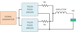
There are cases where the piezo capacitance is so large that very high current is needed to drive it. Multiple PZT driver amplifiers may be connected in parallel to increase the output current. As pictured in Figure 6, two piezo driver amplifiers are connected together to double the output current. A small series resistor, RS, is used to isolate each piezo amplifier from one other. Their resistance is normally between 0.5 and 2 Ω. Two to eight amplifiers may be connected in parallel to increase the output current.
6. Two TS250s are connected in parallel to double the PZT driver current. The “red” connection may be high voltage.
DC Biasing
The resonant technique boosts the piezoelectric driver voltage to where it’s ideal for high-voltage PZT devices. Such voltage is centered at 0 V and has a positive and negative voltage amplitude. This is perfect for piezoelectric devices that require both positive and negative direction movement. Some high-frequency transducers, actuators, and motors require only positive voltage. For example, a PZT needs sinewave voltage that swings from 0 to +130 V. This is equivalent to a 130-V p-p sinewave with a +65-V dc bias.
To easiest way to accomplish this 0- to +130-V sinewave is to choose a piezo transducer driver with a built-in 65-V dc bias (or offset). Simply setting the driver to a desired dc offset voltage (i.e. 65 V) will accomplish this task. Normally, piezoelectric amp drivers with high dc offset voltage usually have limited output current. Another more flexible method allows for high driving current and high dc bias voltage at the same time, which is discussed further down.
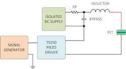
Figure 7 shows the setup using an external dc supply for bias. Such isolated dc power supplies are commonly found in the labs. The supply is connected in series with the piezo actuator driver. Because most drivers aren’t isolated, it’s important to connect the PZT actuator driver’s negative terminal to the ground node along with the function generator’s ground. For that reason, the dc offset supply must be isolated from ground. Most power supplies in the lab are isolated anyway.
7. A dc supply is combined with a TS250 to produce a unipolar high-voltage waveform. The red line indicates a high-voltage node.
The bypass capacitor across the power supply is for high-frequency ac current to pass through as well as to protect the power supply. The capacitance should be large compared to the PZT device capacitance. It’s recommended the bypass capacitance should be at 10 to 100 times the piezo capacitance. This bypass capacitance will affect the resonant frequency, because it’s effectively in series with the PZT capacitance. Therefore, you need to account for the bypass capacitance when calculating the resonant frequency and inductance value. Equations 4 and 5 are modified and shown in Equations 6 and 7.The bypass capacitor voltage rating must meet the maximum dc isolated supply voltage. In addition, the ac voltage must be met. The ac voltage rating is calculated again using Ohm’s law and shown in Equation 8. I is the peak ac current.
The protection resistor, RP, prevents large current flow through the power supply. The dc supply is only for bias and doesn’t need much current. RP is recommended to protect the supply against large ac current and large ac voltage. Because its purpose is to prevent current from flowing to the supply, large resistance may be used (i.e., 10 kΩ). Use larger resistance if the ac voltage is high to prevent ac current from flowing back to the dc supply.
The external supply method allows for the use of a low-voltage, but high-current and high-frequency, piezoelectric driver amplifier combined with a dc supply to set the dc bias. The dc supply doesn’t need to be high current—it’s only for biasing. For example, consider the setup in Figure 7 with 1-µF piezoelectric actuator capacitance and a 0.25-mH resonant inductor, plus a 100-V dc supply. At 10-kHz resonant frequency, the voltage across the PZT is 200 V p-p with ±6.5-A peak current. This is equivalent to 1300-W power. It’s achieved with just a 6.5-A and 6.5-V driver (42 W).
Conclusion
Series resonance using an inductor is a great way to boost voltage when driving high-voltage piezoelectric devices. Adding the inductive element to cancel all or nearly all reactance will reduce the overall impedance. The resonant method can reduce the impedance down to only the resistive component of the piezoelectric element. Piezo transducers generally have low resistance.
Using Ohm’s law again, high current is obtained with a lower-voltage piezoelectric transducer driver. To generate high voltage, the PZT’s large impedance can be exploited. The resonant technique basically transforms a high-current PZT amplifier into a high-voltage piezoelectric driver.
KC Yang is Product Marketing Engineer at Accel Instruments.
About the Author
KC Yang
Product Marketing Engineer
KC Yang is a product marketing engineer at Accel Instruments, which specializes in high-frequency and high-current amplifiers for general lab bench testing. He received a Master of Science in electrical engineering from University of California, San Diego, and a Bachelor of Science in physics from Washington State University. He has published numerous application notes and article.
