Using Nanopower in Smart-Home Applications


Members can download this article in PDF format.
What you'll learn:
- Dealing with battery runtime in smart-home sensors.
- Developing high-efficiency power supplies with a boost converter and a buck-boost converter.
- An example of a nanopowered smoke detector system.
Smart-home applications involve many technical building blocks. Some of these need to be battery-powered because they’re deployed in remote locations, without any cable connections. These include sensors, switches, meters, and portable remote controls. Such devices are usually battery-powered. To build convenient, small-form-factor, reliable, and low-cost systems, power management is critical.
Advances in nanopower technology are making such systems more easily attainable. This article introduces use cases and shows two circuit examples utilizing Analog Devices’s (ADI) MAX77837 and MAX18000 nanopower switching converters.
Living the Dream
Convenience is a deep-rooted desire in human nature. Despite our hard work, we strive to spend our money to make life easier. One area making significant strides is home automation with smart-home technology. We want our homes to serve us better, offering more relaxation, comfort, safety, and environmental benefits.
Traditional home systems like HVAC, security alarms, yard sprinklers, and home entertainment have been around for a while. However, it took interconnected and web-based control to truly enhance convenience. In the past, resetting a sprinkler system for daylight savings might have meant digging out the instruction manual. Now, a single app on our phone can manage everything, often making basic decisions automatically.
Building a Smart-Home Application
Typically, sensors need to be distributed around the house, so that the smart home can see, hear, and feel things. Classic sensors are sensing light, temperature, and movement, while more modern sensors include image recognition and other high-intelligence recognition. Such sensors can detect how many people are in a certain room. And they could detect if a friendly cat decided to walk up to the front door or if a burglar is checking to see through a window if any valuables are available to be stolen.
To save cost and provide flexibility, these sensors should run without wires attached to them. This way, sensors may be deployed easily in existing homes and the perfect location can be utilized. With wireless communications, such as Wi-Fi or Bluetooth, data communication isn’t a difficult problem to solve nowadays.
However, every sensor needs power, and supplying it remains a challenge for most applications. Energy harvesting with common photovoltaic cells are used, but batteries are very often still the preferred choice. The biggest problem with smart-home systems is battery runtime.
To make simple batteries practical and photovoltaic cells cost-effective, sensors need highly efficient power supplies. Both the standby current and the efficiency during full load operation are crucial to the design of any smart-home system.
Very Efficient Power Supply Using a Single Battery Cell Boost Converter
A simple way of powering a distributed sensor is using a primary cell, which is a disposable, nonrechargeable battery. Such batteries offer a good compromise between circuit cost, hardware components, and cost of ownership (such as cost and effort of replacing or recharging batteries).
Typically, these primary cell batteries provide a voltage of 1.5 V. This is when the batteries are still fresh. Upon discharge, the battery voltage reduces to values below 0.8 V. Different battery chemistries show different voltage curves during their discharge cycle. But generally, batteries have hardly any usable energy left, as the voltages drop below 0.8 V.
Many electronic circuits need a higher operating voltage than 0.8 V. To better match the supply voltage with the operating voltage, multiple battery cells may be used in series. However, multiple cells cost more money and they require more space than just one battery cell.
For this reason, very efficient boost regulators are available. They boost a typical primary battery cell voltage in the range of 0.8 to 1.5 V, to a voltage that a smart-home application can actually be supplied with, such as 3.3 V or even 5 V. Figure 1 shows this type of miniaturized boost-converter circuit using the MAX18000.
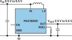
This circuit is compact and only requires a few external components. The DC-DC converter IC itself comes in a 1.07- × 1.57-mm package. The boost converter is equipped with two internal 3.6-A switches. Quiescent current is only 512 nA, while the output voltage is up and running. Peak efficiency is 95% and low load efficiency, with higher than 2- µA load current, is still above 90%. The input operating voltage ranges from 0.5 to 5.5 V, making it possible to boost very low battery voltages such as 0.8 V, to useful higher system voltages.
Very Efficient Power Supply Using a Buck-Boost Converter
Other sensor applications run with multiple battery cells or possibly a Li-ion battery. Such voltages are a bit higher than in the example above. Typical values are around 3.7 V in the state of a fully charged Li-ion battery. As the cells are being discharged, a voltage of 2.8 V is about the minimum, before the energy stored in such a cell is depleted. This voltage range, from 2.8 to 3.7 V requires a buck-boost solution to generate a nominal 3.3 V to run common circuit electronics for a typical sensor. This is why buck-boost converters became especially popular with the rise of Li-ion batteries.
A similar need arises when using three primary cell batteries with 1.5 V in series. In total, they will provide 4.5 V when fully charged, but when nearly discharged, the batteries only provide roughly 2.4 V. Generating a fixed 3.3 V for the sensor again requires a buck-boost solution.
Figure 2 shows a buck-boost solution with the MAX77837. This solution requires few external components, making the required printed-circuit-board (PCB) area extremely small. Also, the chip itself comes in a very small package that requires only 1.84 × 1.03 mm. If a sensor manufacturer would like to use a package with a larger pitch (distance between the pins), a 2.5- × 2-mm QFN package is available.
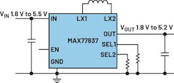
To make the battery last as long as possible, this solution only requires a quiescent current of 430 nA typical. When shut down, the power-conversion IC consumes a mere 10 nA. This may be useful for applications that have an energy-storage capacitor next to the main battery. The DC-DC converter can then be in a shutdown mode for some period of time before it reactivates and charges the capacitor up again. Such a scheme may provide additional energy savings over time, and it could make the operation time with a given battery even longer.
Simplifying Design with Circuit Simulation
When designing a battery-powered sensor, it’s essential to answer basic questions about the capabilities and limitations of the power circuit. Circuit calculation and simulation are valuable at this stage, as they save time and reduce the risk of starting a hardware design with an unsuitable integrated circuit.
ADI offers the free EE-Sim Power Tool to get started. With this tool, a user need only enter input voltage, output voltage, and current requirements, and a suitable circuit is calculated in no time. Figure 3 shows an example of a circuit simulation result within EE-Sim Power.
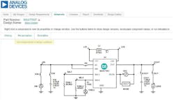
Based on this circuit calculation and based on actual external components, circuit simulation can be performed, providing waveforms of different voltages and currents. Advanced simulations such as load step, AC loop, line transient, and efficiency may also be performed.
Hardware to Get Started With
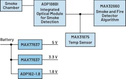
Theory and simulation are important, but real-world hardware can be quite different. In addition to evaluation boards for individual power converters, complete, practical sensor systems are available for evaluation. One is a smoke detection system: “Multistandard Micropower Verified Smoke Detection System-on-Module” shows the MAX77837 and the ADP162 to power a smoke detector. It consists of the ADPD188BI integrated optical module for smoke detection, the MAX32660 with a smoke and fire detection algorithm, and the MAX31875 digital temperature sensor (Fig. 4).
All of the design files can be downloaded here, providing an easy path to creating a smart-home sensor with nanopower features. This fully optimized and verified sensor hardware includes the necessary software and demonstrates the capabilities of the power management circuitry.
Even Smarter Sensors Loom on the Horizon
Power management is crucial for enabling the smart home. It ensures highly efficient power conversion, extending the runtime of small, low-cost batteries. These sensors offer numerous features, including robust connectivity.
Today, buck, boost, and buck-boost converters require extremely low quiescent current to make battery or energy-harvesting-powered systems practical for many sensor applications. Innovations in semiconductor processes and integrated-circuit design make this achievable.
This is just the beginning. Numerous upcoming innovations will enable even smarter sensors in the connected home, all driven by advances in power management.
Read more articles in the TechXchange: Low-Power Battery Technology.
About the Author

Frederik Dostal
Power-Management Technical Expert
Frederik Dostal is a power-management expert with more than 20 years of experience in this industry. After his studies of microelectronics at the University of Erlangen, Germany, he joined National Semiconductor in 2001, where he worked as a field applications engineer, gaining a lot of experience in implementing power-management solutions in customer projects. During his time at National, he also spent four years in Phoenix, Arizona (USA), working on switch-mode power supplies as an applications engineer.
In 2009, he joined Analog Devices, where since then he held a variety of positions working for the product line and European technical support, and currently brings in his broad design and application knowledge as a power-management expert. Frederik works in the ADI office in Munich, Germany.
Also check out my:
Comment About the Article
To join the conversation, and become an exclusive member of Electronic Design, create an account today!

Leaders relevant to this article: