High-Voltage Driver Satisfies Unique Loads and Eases Design-In “Surprises”
Designers of lower-voltage systems (in the tens of volts) who find themselves in the world of higher-voltage systems eventually find out that it’s a different regime in many ways. Soon, you’re in world of creepage and clearance minimums, regulatory mandates, and even “strange” behavior of materials.
In some applications, the need for higher voltages is driven by having to reduce current demands for a given delivered power level, and thus reduce resistive (IR) and dissipative (I2R) losses. But in many cases, it’s the inherent, unavoidable physics of the load, such as a scientific instrumentation, piezoelectric actuators and other capacitive loads, electroluminescent displays, or MEMS devices, all of which may require those higher voltages to function.
Boosting a standard function such as a driver up from a few tens of volts to several hundred is a challenge. While you can take an available low-voltage driver and add a high-voltage output-stage transistor, it usually results in marginal performance as there are many static and dynamic considerations, transients, and more about which to worry.
Apex Driver IC Spans 30 to 300 V
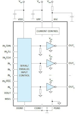
That’s’ where the AIC1513 from Apex Microtechnology can provide a low-headache solution. This general-purpose, high-voltage driver IC has eight parallel push-pull outputs for the cited loads and similar varieties (Fig. 1). Its operating voltage ranges from 30 up to 300 V and each output can handle currents up to 40 mA.
The device, in a 32-pin, 5- × 5-mm VQFN package, has been designed for harsh industrial applications to broaden its application range: It’s high-voltage push-pull outputs are protected against possible latch-up by using the bulk-drain diodes of the output MOSFETs and their full dielectric isolation. In addition, the N-channel MOSFET outputs offer reduced power consumption compared to alternative output approaches.
External, user-selected output resistors can be used to limit the maximum power dissipation, thereby enabling the outputs to be run in parallel. The IC also allows for the use of an external resistor to set the switch-on time of the outputs and provides protected direct-transistor gate inputs.
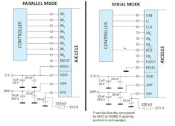
For applications that require more than just those eight outputs (you can never have too many, or it’s nice to the option for more, right?), the AIC1513 inputs can be configured to operate in either parallel or serial mode by a logic-level setting of a discrete mode pin (Fig. 2).
When in parallel mode, each high-voltage output is controlled by a dedicated input pin. In serial mode, internal shift registers convert the data provided by a clocked input stream to the desired high-voltage output. This also enables several devices to be daisy-chained if more than eight parallel outputs are needed.
About the Author

Bill Schweber
Contributing Editor
Bill Schweber is an electronics engineer who has written three textbooks on electronic communications systems, as well as hundreds of technical articles, opinion columns, and product features. In past roles, he worked as a technical website manager for multiple topic-specific sites for EE Times, as well as both the Executive Editor and Analog Editor at EDN.
At Analog Devices Inc., Bill was in marketing communications (public relations). As a result, he has been on both sides of the technical PR function, presenting company products, stories, and messages to the media and also as the recipient of these.
Prior to the MarCom role at Analog, Bill was associate editor of their respected technical journal and worked in their product marketing and applications engineering groups. Before those roles, he was at Instron Corp., doing hands-on analog- and power-circuit design and systems integration for materials-testing machine controls.
Bill has an MSEE (Univ. of Mass) and BSEE (Columbia Univ.), is a Registered Professional Engineer, and holds an Advanced Class amateur radio license. He has also planned, written, and presented online courses on a variety of engineering topics, including MOSFET basics, ADC selection, and driving LEDs.


