Selecting the Best Point-of-Load Converters for Automotive SoC Power Trees
What you’ll learn:
- The power requirements of the latest automotive SoCs.
- How to select point-of-load (PoL) converters for automotive SoC power rails
High-end processors at the heart of advanced driver-assistance systems (ADAS) and infotainment systems continue to escalate power demands. In these contexts, a system-on-chip (SoC) tends to require a number of different power rails, with currents ranging from as high as hundreds of amperes to several milliamps.
To smoothly and efficiently supply SoC power rails, it’s critical to carefully design the pre-regulator in the system. But engineers also need to understand the intricacies of selecting optimal point-of-load (PoL) converters.
SoC Power Requirements: Current, Transients, and Voltage Tolerance
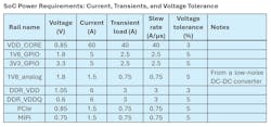
Before discussing component selection, it’s important to review the power requirements of the SoC in question. The table lists the power needs of a typical high-performance automotive SoC.
The most important parameter in the table is the maximum current rating, as this determines what IC will work best. On the one hand, a DC-DC converter must be rated for a nominal output current (IOUT) equal to or greater than the rail’s current rating to guarantee the best performance. However, to get the most cost-effective solution, the engineer should not select a part that provides more than 150% of the current required by the rail. With these considerations in mind, a limited selection of chips can typically match the system requirements.
To further optimize IC selection, designers must take the other requirements into account. Both the transient load and voltage tolerance also play an important role when selecting a device. If the transient-load magnitude is relatively high (>30% of the rated current) and the voltage tolerance is tight (<5%), it’s essential to choose a device that has excellent load transient response.
>>Download the PDF of this article
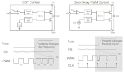
These devices usually implement advanced control methods (Fig. 1), such as constant-on-time (COT) or zero-delay PWM (ZDP). These controls schemes have very fast transient-load response, and they minimize the amount of output capacitance needed to meet the tolerance requirement. Note that the voltage tolerance includes the PoL converter’s DC accuracy, transient-load response, and IR drop.
Choosing the Right Point-of-Load Converter for Each SoC Power Rail
In driver-assistance and infotainment systems, cost and scalability are key. In these cases, discrete DC-DC converters are the best approach for the power supply as they tend to be very flexible.
Their counterparts, power-management ICs (PMICs), integrate several converters into a single device and can simplify the design. The tradeoff is that they’re very rigid and may not fit the specific demands of the application. Discrete PoL devices can be placed close to the SoC, facilitating a good power-delivery network (PDN). Since converters dissipate energy in the form of heat, by using discrete ICs the heat sources can be spread out to ease thermal management.
VDD_CORE Rail: Handling High Currents with Multi-Phase Converters
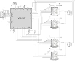
Starting with the VDD_CORE rail, the maximum current rating is 60 A, which is relatively high. To supply high current and low output voltages, multi-phase voltage regulators are preferable (Fig. 2). At the heart of the voltage regulator is a controller that must be paired with DrMOS power stages, which are monolithic half-bridges with built-in power MOSFETs and gate drivers.
Automotive-grade controllers that use advanced control techniques to minimize disturbances to the power rail achieve excellent transient response performance. In addition, DrMOS power devices are efficient and compact solutions for heavy-duty loads.
In this case, when you have output current of 60 A, it’s recommended to couple the controller with a pair of power stages—for instance, the Intelli-Phase family of power ICs from Monolithic Power Systems—to create a dual-phase voltage regulator capable of supporting such high loads.
The remaining power rails require significantly lower current. Thus, regular monolithic step-down converters can be used to convert the 5V bus voltage to the required voltage for each rail.
Optimizing 1V8_GPIO and 3V3_GPIO Rails for Cost and Performance
The 1V8_GPIO and 3V3_GPIO rails each require 5 A of supply current, but the transient-load and voltage-tolerance specifications aren’t as strict as the other power rails feeding into the SoC. But choosing the right PoL converter for these power rails remains important. In this case, it makes sense to use a frequency-configurable, synchronous step-down converter that can supply up to 6 A of output current in a compact package.
By switching as fast as 1 MHz or more, the DC-DC converter makes it possible to utilize physically smaller passive components that can be used to save both cost and area. It’s also preferable to use PoL converters that feature peak-current-mode (PCM) control and internal compensation to deliver smooth, stable voltages to the load. These parts are designed to protect against short circuits and other overcurrent conditions as well as sudden spikes of voltage and overheating.
Choosing PoL Converters for the 1V8_Analog, PCIe, and MIPI Rails
The 1V8_analog rail is more challenging, as it supplies power to sensitive analog circuitry in the SoC that needs a stable, low-noise source. It also requires a maximum current of 1.5 A, which is too high to be supplied from a low-noise, low-dropout (LDO) linear regulator. Such an LDO could overheat under the hood of a vehicle, where the ambient temperature can be 85°C or higher.
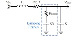
A highly efficient step-down converter is critical for this power supply, but its output noise must be attenuated to meet the design requirements. To provide the required attenuation for the low-noise supply, a second-stage filter must be added to the converter’s output (Fig. 3). The SoC hardware manual should provide guidance on how to design the filter for this supply rail, though there are also resources that describe how to design the second-stage filter for low-noise power supplies.
For instance, the MPQ2178-AEC1 is able to supply low-current rails and operates at a constant 2.4-MHz switching frequency (fSW) during steady-state conditions. The device also features advanced COT control, giving it excellent response times during transient loads. Furthermore, the PoL converter can be used for the PCIe and MIPI supply rails because they have similar requirements to the 1V8_analog rail, but those rails don’t require the second-stage output filter.
DDR Memory Supply Rails: Meeting Stringent Voltage Tolerances
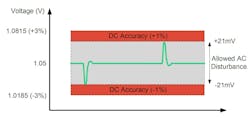
Finally, the two DDR memory supply rails require 6 A of output current and excellent transient-load response. The DDR_VDD rail has a 3% voltage-tolerance requirement—with 1.05 V of nominal rail voltage, it only allows for a ±31.5-mV deviation.
The DDR_VDDQ rail has a higher voltage tolerance at 5%. However, with a 0.6-V nominal voltage, the allowed deviation is also very narrow at 30 mV. Furthermore, the DC accuracy of the selected IC must be subtracted from the allowed voltage deviation, leaving even less room for disturbances caused by load transients (Fig. 4).
It’s important to choose a DC-DC converter IC with high accuracy of 1% across the full operating range, as well as a very fast control loop. To take care of these power requirements, it makes sense to use a step-down converter running a ZDP control loop that achieves fast transient response, capable of keeping the voltage disturbance under ±15 mV with minimal output capacitance.
The Keys to Selecting DC-DC Converters for Automotive SoCs
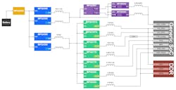
By evaluating the requirements of the different power rails and choosing the best power converters for the job, the SoC power tree can be updated to reflect the final architecture. Then the hardware engineer can start doing the calculations for the required passive components, such as power inductors and output capacitors. Figure 5 shows the final power tree, including the pre-regulator design, for a high-performance SoC.
The first step is to identify the key requirement for each rail in the automotive SoC power tree, whether it’s efficiency, accuracy, noise, or even cost. Then the system architect must identify the optimal device to best match the key requirements under the hood of the vehicle. Many suppliers offer an easy way to compare a wide range of AEC-Q100-qualified controllers and converters and filter them out based on different requirements.
>>Download the PDF of this article
About the Author
Francesc Estragués
Senior Technical and Marketing Engineer, Monolithic Power Systems
Francesc Estragués is Senior Technical and Marketing Engineer at Monolithic Power Systems. He received his BSc in Industrial Electronics from the Universitat Politecnica de Catalunya and has been working in hardware design for the past three years.

