Active Balancing ICs Optimize Battery Stack Performance, Extend Run Time
Typically, the individual cells in a battery have somewhat different capacities and may be at different levels of state of charge (SOC). Without balancing, the cell of smallest capacity is a “weak point”; it can be easily overcharged or over-discharged while cells with higher capacity undergo only a partial cycle. For the higher capacity cells to undergo full charge/discharge cycle of the largest amplitude, balancing should “protect” the weaker cells; so that in a balanced battery, the cell with the largest capacity can be filled without overcharging any other (i. e. weaker, smaller) cell, and it can be emptied without over-discharging any other cell. Battery balancing is done by transferring energy from or to individual cells, until the SOC of the cell with the lowest capacity is equal to the battery's SOC. Linear Technology’s LT8584 active battery balancer along with Linear’s LTC6804 multicell battery stack monitors (BSM) ICs provide a system solution for battery management and presentation of operational data.
Related Articles
- Power Bank – Power On-The-Go (Part 2)
- Lithium (Ion) Battery Safety and Required Regulatory Testing
- Future Electric Vehicle Success Will Depend on Its Energy Source
- Battery Pack with Cell Balancing
- Battery Technology Holds High Potential for EVs
- Top 10 Tidbits of Battery Wisdom
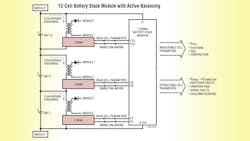
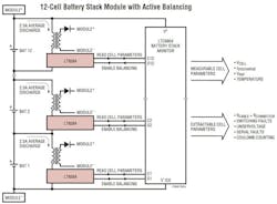
The LT8584 is a monolithic flyback DC/DC converter that actively balances high voltage stacks of batteries (Fig. 1). The high efficiency of this switching regulator significantly increases the achievable balancing current while reducing heat generation. Active balancing also allows for capacity recovery in stacks of mismatched batteries, which is not attainable with passive balancing systems. In a typical system, the LT8584 can recover up to 99% of the total battery capacity.
The LT8584 includes an integrated 6 A, 50 V NPN power switch, reducing the design complexity of the application circuit. The IC runs completely off of the cell that it is discharging, removing the need for complicated biasing schemes commonly required for external power switches. The IC’s enable pin (DIN) works seamlessly with the LTC680x family of battery stack voltage monitoring ICs.
Switch Protection
Several protection features reduce the likelihood of permanent damage to the internal power NPN switch. A short-circuit detector detects if the power NPN switch turns off prematurely due to a short in the primary side winding. A high-impedance detector monitors how long the power NPN switch has been on. If the switch remains on longer than 50 μs, the switch maximum on-time, it sets the switch error latch. The Overvoltage protection (OVP) circuitry dynamically clamps the NPN collector’s SW pins to 50 V. This protects the internal power switch from entering breakdown and causing permanent damage. The clamp is also used as a primary-side snubber to absorb the leakage inductance energy.
The LT8584 also provides system telemetry including current and temperature monitoring when used with the LTC680x IC family. When the LT8584 is disabled, less than 20 nA of total quiescent current is typically consumed from the battery.
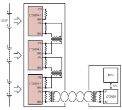
A member of the LTC680x family, the LTC6804, is a third generation multicell battery stack monitor that measures up to 12 series connected battery cells with a total measurement error of less than 1.2 mV (Fig. 2). The cell measurement range of 0 V to 5 V makes the LTC6804 suitable for most battery chemistries.
The LT6804 monitors each individual cell in the stack and communicates this information through a proprietary serial bus to a central processing unit. If a cell begins to approach the allowable voltage limit, an LTC6804 commands the LT8584 to actively shunt the charging current and return energy back to the battery stack. Therefore, instead of the energy being lost as heat, it is reused to charge the rest of the batteries in the stack. The architecture of the LT8584 also solves the problem of reduced run time when one or more of the cells in the stack reaches the lower safety voltage threshold before the entire stack capacity is extracted. Only active balancing can redistribute the charge from the stronger cells (cells with higher voltage) to charge the weaker cells. This allows the weaker cells to continue to supply the load, extracting more than 96% of their entire stack’s capacity.
The LT8584 has an integrated 6 A switch designed to operate as a boundary mode flyback converter and provides 2.5 A average discharge current. The average discharge current is also scalable by using multiple LT8584s to balance each cell. Each battery in the stack requires an LT8584 active cell balancer circuit (Fig. 1).
The LT8584 flyback topology allows the charge to return between any two points in the battery stack. Most applications use a module approach and return the charge to a local set of 12 series-connected cells monitored by a 12 channel BSM IC (LTC6804), where the output of the flyback converter is designated as VMODULE. The entire battery stack is then constructed using several 12-cell modules connected in series. A second approach is to return the charge to the entire battery stack, where the flyback output is designated as VSTACK. A final option is to return the charge to an auxiliary power rail, designated as VAUX.
The LT8584 has two modes of operation—selectable by the MODE pin—that can be seamlessly integrated with the LT6804. In simple mode, the LT8584 discharger is toggled on/off using a logic input pin. In serial mode, the LT8584 allows the user to measure the discharge current and the die temperature, in addition to the cell voltage.
Measuring Cell Voltage
An LTC6804 can measure up to 12 series connected battery cells at voltages up to 4.2 V with 16-bit resolution and better than 0.04% accuracy. This high precision is maintained over time, temperature and operating conditions by a sub-surface Zener voltage reference similar to references used in precision instrumentation. When stacked in series, the LTC6804 enables the measurement of every battery cell voltage in large high voltage systems. Six operating modes are available to optimize update rate, resolution and the low pass response of the built-in third order noise filter. The fastest mode, measures all cells within 290 μsec. For greater noise reduction you can employ longer data acquisition rates.
You can interconnect multiple LTC6804s over long distances and operated simultaneously, using Linear Technology’s proprietary 2-wire isoSPI™ interface. Integrated into every LTC6804, the isoSPI interface provides high RF noise immunity up to 1 Mbps and up to 100 meters of cable, using only twisted pair. Two communication options are available: with the LTC6804-1, multiple devices are connected in a daisy chain with one host processor connection for all devices; with the LTC6804-2, multiple devices are connected in parallel to the host processor with each device individually addressed. The LTC6804 can be powered directly from the battery, or from an isolated supply.
The LTC6804 is intended to minimize power consumption, especially during long-term storage where battery drain is unacceptable. In sleep mode, the LTC6804 draws less than 4 μA from the batteries. General-purpose I/O pins are available to monitor analog signals, such as current and temperature, and can be captured simultaneously with the cell voltage measurements. Additional features include passive balancing for each cell with a programmable balancing timer for up to 2 hours, even when the LTC6804 is in sleep mode. The LTC6804 interfaces with external I2C devices such as temperature sensors, ADCs, DACs and EEPROM. A Local EEPROM can be used to store serialization and calibration data, which enables modular systems.
The LTC6804 is powered via two pins: V+ and VREG. The V+ input requires voltage greater than or equal to the top cell voltage, and it provides power to the high voltage elements of the core circuitry. V+ can be directly connected to the top cell of the battery stack, or to an external supply. The VREG input requires 5 V and provides power to the remaining core circuitry and the isoSPI circuitry. The VREG input can be powered through an external transistor, driven by the regulated DRIVE output pin. Alternatively, VREG can be powered by an external supply.
The LTC6804 surpasses the environmental, reliability and safety demands of automotive and industrial applications. It is fully specified for operation from -40 °C to 125 °C. It has been engineered for ISO 26262 (ASIL) compliant systems and a full set of self-tests ensure that there are no latent fault conditions. To accomplish this, the LTC6804 includes a redundant voltage reference, extensive logic test circuitry, open wire detection capability, a watchdog timer and packet error checking on the serial interface.
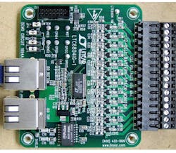
The LTC6804 is offered in a small 8 mm x 12 mm surface mount device. A demonstration board is available, as shown in Fig. 3.
As an option, there is Linear Technologies LTC6820 isoSPI transceiver that enables bidirectional transmission of the Serial Peripheral Interface bus (SPI) across an isolated barrier up to 100 meters. With the LTC6820, the SPI data is encoded into a differential signal, which is then transmitted via twisted pair and a simple, inexpensive Ethernet transformer. The LTC6820 supports SPI data rates up to 1 MHz, using matched source and sink currents to eliminate the need for a transformer center tap and to reduce EMI. The drive currents and the comparator thresholds are set with two resistors, allowing the system to be optimized for cable length and signal-to-noise performance. Battery management systems using the LTC6804 can interface to external components, such as microcontrollers, via the LTC6820.
About the Author

Sam Davis
Sam Davis was the editor-in-chief of Power Electronics Technology magazine and website that is now part of Electronic Design. He has 18 years experience in electronic engineering design and management, six years in public relations and 25 years as a trade press editor. He holds a BSEE from Case-Western Reserve University, and did graduate work at the same school and UCLA. Sam was the editor for PCIM, the predecessor to Power Electronics Technology, from 1984 to 2004. His engineering experience includes circuit and system design for Litton Systems, Bunker-Ramo, Rocketdyne, and Clevite Corporation.. Design tasks included analog circuits, display systems, power supplies, underwater ordnance systems, and test systems. He also served as a program manager for a Litton Systems Navy program.
Sam is the author of Computer Data Displays, a book published by Prentice-Hall in the U.S. and Japan in 1969. He is also a recipient of the Jesse Neal Award for trade press editorial excellence, and has one patent for naval ship construction that simplifies electronic system integration.
You can also check out his Power Electronics blog.


