11 Myths About E-Fuse Circuit Protection
What you’ll learn:
- Benefits of an e-fuse solution.
- Optimal voltage range for e-fuse applications.
- Target applications for e-fuse devices.
The trend toward higher bus voltages creates the need for a robust circuit protection strategy to protect electric systems. An e-fuse solution offers many system-level benefits over traditional mechanical solutions. The technology can be employed in a range of applications including automotive, especially when dealing with electric vehicles (EVs). Unfortunately, a few myths about this technology need to be addressed.
1. E-fuse is exclusively a MEMS-based technology.
MEMS technology is used in low-current power switches. However, for a true solid-state solution with the ruggedness and reliability necessary for use in high-voltage systems in the 300- to 1500-V range, a silicon-carbide (SiC)-based solution is the preferred technology for the power switch. SiC technology is best suited for a high-voltage e-fuse due to its low conduction loss and ruggedness to electrical transients.
2. E-fuse is only used in low-current applications.
The versatility of SiC enables high-current solutions in the tens of amps using discrete MOSFETs, to hundreds of amps using power modules. Among the advantages of SiC over silicon are the lower on-state conduction losses over temperature, lower off-state leakage current, higher temperature operation, and higher thermal conductivity. These make SiC a great fit in a high-voltage, high-current, solid-state circuit protection solution.
3. E-fuse can’t support high currents.
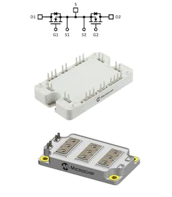
The maturity and widespread adoption of SiC technology has enabled the growth of solid-state solutions in high-voltage and high-current applications. The availability of SiC power modules in a back-to-back, common-source configuration arms designers with the capability of developing e-fuse solutions that support over 600-A continuous current with bidirectional voltage and current blocking capability (Fig. 1).
4. E-fuse and a semiconductor fuse are one and the same.
While both are designed to protect sensitive electronic loads, the technology behind them is quite different. A semiconductor fuse is a fuse with a low I2t rating and low let-through current. The term “semiconductor” in the name describes the type of load it’s optimized to protect. An e-fuse is an electronic fuse consisting of semiconductors, including control and measurement circuits, high-voltage switching devices, and, optionally, software for configurability and diagnostics.
In addition to using completely different technologies, a blown semiconductor fuse requires replacement since it’s a one-time-use device, while an e-fuse is a resettable device that doesn’t need to be replaced in a system. Despite a semiconductor fuse having a faster response time over traditional fuses, it’s still orders of magnitude slower than an e-fuse.
5. E-fuse isn’t robust to short-circuits.
To the contrary, other protection devices are triggered by the consequence of a high short-circuit current, such as heat, while an e-fuse is an electronic solution that directly measures the current itself, not a secondary effect of the current. This provides fast, precise, and deterministic responses to overloads and short-circuits.
6. E-fuse is only relevant in automotive applications.
While e-fuse is beginning to gain traction in automotive, several non-automotive applications are migrating to solid-state protection technologies. Any battery-powered system or system powered by a low-impedance energy source that can deliver high currents will benefit from an e-fuse solution. Beyond electric vehicles, a SiC-based e-fuse protects many different applications from microgrids to aviation systems to distributed energy resources.
7. E-fuse circuit protection can’t be used in safety applications.
An e-fuse can further enhance the safety of a system. With its superior current-measurement accuracy, the low let-through current and energy reduce the severity caused by a downstream fault. There are no internal moving parts that could result in arcing within the device due to its solid-state design.
The fast response time reduces and may even eliminate the risk of arcing in loose connections within the system. In addition, an e-fuse quickly isolates faulted loads, allowing the rest of a system to continue stable operation.
8. E-fuse isn’t as reliable as fuses, circuit breakers, and relays.
Circuit-protection devices and electromechanical power disconnect switches typically require service during the lifecycle of a device or system. They may be one-time trip devices that need user intervention to manually reset, or they simply require service due to their limited life. These traditional solutions suffer from degradation due to mechanical shock, vibration, contact bounce, and contact oxidation from insufficient wetting current.
On the other hand, e-fuse is resettable and doesn’t exhibit degraded reliability from mechanical stresses. An e-fuse interrupts short-circuits at significantly lower currents, minimizing the stress in the downstream circuit that it’s protecting. A system protected by an e-fuse increases system reliability by using fewer system-level components, which reduces the risk for defects or failures.
9. E-fuse doesn’t offer compelling advantages over existing solutions.
While existing solutions generally have a lower voltage drop and power dissipation than an electronic solution, an e-fuse outperforms existing solutions in nearly every other relevant category. The fast response time, resettable capability, high temperature operation, and solid-state design were covered above. Other benefits include superior performance in DC systems, controllability including pulse-width-modulation (PWM) capability, system measurement, and monitoring for both functional operation and state-of-health diagnostics.
For systems using a pyro fuse with fast response time and high breaking capacity, an e-fuse complements the pyro fuse quite well. With a much faster response time, an e-fuse limits the pyro fuse’s exposure to a short-circuit, allowing it to only be used as a last resort.
10. E-fuse is difficult to implement.
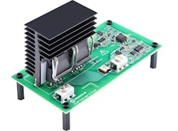
An e-fuse is a design based on established electronics design practices. Microchip offers design support tools such as a high-voltage E-Fuse Demonstrator Board and its design files, including software, to help designers in the development of their e-fuse solution (Fig. 2).
11. E-fuse is an expensive solution.
In determining the cost of circuit protection, it’s important to consider the total cost at the system level beyond the individual circuit-protection device. The cost of fuse holders, wiring from the protected circuit to the fuse, access panels, seals, fasteners, and high-voltage interlock (HVIL) circuits should be accounted for when determining the total cost of a fuse-based implementation. Similarly, with high-current contactors, an economizer is commonly used to minimize the power dissipation in the coil.
Beyond material costs, the cost of installation and service are important considerations in several applications. Servicing these systems requires qualified personnel trained to work with high voltage. In the case of an EV, the ability for an e-fuse to clear an overcurrent fault and reset may prevent the EV from breaking down, providing a more reliable solution. In the end, you may find a SiC-based e-fuse circuit-protection solution to not only be cost-competitive, but also enable further enhancements of system-level integration and optimizations.


