Tiny Gas-Discharge Tube Enhances Voltage-Surge and Transient Protection
What you’ll learn:
- Why a gas-discharge tube is an important component for overvoltage protection.
- The history of spark gaps—predecessors to GDTs—includes a role in famous movies.
- How a new, compact, surface-mount GDT protects against voltage surges and transients.
Circuit protection is like insurance—you really don’t need it until you unexpectedly do, and then you’re very glad you have it. Such protection falls into two broad categories:
- Protection against overcurrent (the common thermal fuse and electronic fuse are often the first or last line of defense in many cases).
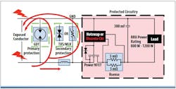
- Protection against overvoltage using devices such as metal-oxide varistors (MOVs), gas-discharge tube (GDTs), and surge arrestors (Fig. 1).
In the big picture overview, an ideal protection device exists in two dramatically different modes:
- It’s electrically invisible when not activated, adding little or no resistance, capacitance, or inductance to the line it’s protecting.
- When activated by an overcurrent or overvoltage event, the device quickly transitions to a mode where it attenuates or diverts the excess current or voltage. Depending on the device, it may then revert to its quiescent or watchful state when the fault event is over.
GDTs are nearly ideal with respect to these two requirements, as they “crowbar” and quickly become a short circuit across their terminals when a transient voltage surge occurs, then revert to gigohm-level resistance when it passes.
The response of GDTs follows a well-defined time versus terminal voltage curve: When the voltage across the terminals exceeds the device’s sparkover voltage, the inert gas in the GDT (such as neon or argon) becomes fully ionized and no longer functions as an insulator. Instead, conduction across the device terminals occurs in less than a microsecond (Fig. 2).
Spark Gaps: The Cinematic GDT Predecessors
Circuit-board GDTs are very different from the large, imposing, and dramatic spark-gap devices (their historical predecessor) that’s embedded in our collective memories due to movie classics such as Frankenstein (1931). There, they somehow served (it’s not clear how) to help capture and channel energy from lightning to spark life into Dr. Frankenstein’s creation (Fig. 3).
Spark gaps were used by early experimenters long before the concept of electronics as we know it today existed, when basic electricity was a barely understood phenomenon under investigation by scientists and those experimenters. These include Benjamin Franklin and his famous kite experiment (1752), Humphrey Davy’s use of spark arcing for electrolysis to decompose substances to their elements (early 1800s), and Michael Faraday’s work (also early 1800s). Despite their age and the “antique” status of their basic operating principle, GDTs are very viable for new applications, as they evolved and have been modernized to meet the need of today’s circuits and systems.
Bourns’ New Mini Gas Discharge Tubes
That’s where the Bourns Model GDT21 Series of new ultra-compact GDTs finds a role (Fig. 4). These two-electrode devices are designed to provide maximum impulse-voltage limiting in a space-saving EIA 1206 surface-mount package (3.3 × 1.6 mm). They’re available with six sparkover-voltage ratings between 150 and 600 V (±30%).
The RoHS-compliant, UL-recognized passive devices feature very low capacitance (under 0.3 pF) for minimal insertion loss. This makes them well-suited for assuring signal integrity in communication systems as well as for industrial controls, set-top boxes, HVAC systems, and antenna front ends, among other applications. They’re designed to function over a wide operating temperature range from −40 to +105°C
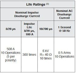
One concern with nearly all protection devices is how many “hits” they can tolerate, as some are one-shot devices by design (the common thermal fuse), while others can withstand repeat events. Bourns addresses this question with a table that applies to all six GDTs in the series and defines test conditions as well (see table).
Clearly, GDTs have come a long way from their historical roots as well as portrayal in movies, to meet the needs of today’s PCBs and requirement for SMT packaging.
References
Bourns, “Advancing GDT Technology to Meet Higher Surge and Multi-level Protection Requirements”
Bourns, “GDT Brochure”
About the Author

Bill Schweber
Contributing Editor
Bill Schweber is an electronics engineer who has written three textbooks on electronic communications systems, as well as hundreds of technical articles, opinion columns, and product features. In past roles, he worked as a technical website manager for multiple topic-specific sites for EE Times, as well as both the Executive Editor and Analog Editor at EDN.
At Analog Devices Inc., Bill was in marketing communications (public relations). As a result, he has been on both sides of the technical PR function, presenting company products, stories, and messages to the media and also as the recipient of these.
Prior to the MarCom role at Analog, Bill was associate editor of their respected technical journal and worked in their product marketing and applications engineering groups. Before those roles, he was at Instron Corp., doing hands-on analog- and power-circuit design and systems integration for materials-testing machine controls.
Bill has an MSEE (Univ. of Mass) and BSEE (Columbia Univ.), is a Registered Professional Engineer, and holds an Advanced Class amateur radio license. He has also planned, written, and presented online courses on a variety of engineering topics, including MOSFET basics, ADC selection, and driving LEDs.


