"STATESET" SPICE Model Ensures Simulation of Nonlinear Circuits
Find a downloadable version of this story in pdf format at the end of the story.
A major new “STATESET” SPICE model used in fast average modeling ( http://www.intusoft.com/DSP/Average_Models.pdf) for power supplies and related control systems guarantees DC convergence for nonlinear circuits. Many nonlinear circuits have more than one stable operating point solution during SPICE simulation, which uses the “nodeset” statement to suggest an initial value. However, the suggestion must be released when the simulator starts doing iterations in order to account for the branch currents. STATESET, on the other hand, creates a new circuit branch in which the element output is initialized during the entire DC operating point calculation. Once the operating point is calculated, the input of the STATESET branch connects to its output so the AC and Transient analyses can proceed. STATESET is essentially a gain element that has two terminals, input and output, where a signal flows from the input to the output in a control-system fashion.Though STATESET is a simple concept, standard SPICE simulators can't handle the problem STATESET resolves. Users of XSPICE-enabled simulators can easily add a code model (http://www.intusoft.com/best.htm) that achieves the desired result. Other SPICE simulators (Pspice and Hspice) need to add a new primitive element.
STATESET UNVEILED
One of the most daunting non-linearities is the “Middlebrook” equation [1] that describes a peak current controller as a function of average current at its terminal voltages. This equation has more than one stable solution, which can cause the SPICE DC operating point solution to become unstable, and therefore unable to converge.
A linear pulse width modulator (PWM) average model sets output voltage and input current to functions of the input duty ratio. The simplest of all models results when the switched inductor current is continuous, referenced as continuous conduction mode (CCM). The process is governed by Z-Transform theory, requiring a zero-order hold and a limiter to constrain the duty ratio between 0 and 1. The current and voltage functions are nonlinear, but they can be made linear for the DC solution by using a STATESET element shown in Fig. 1.
Normally the duty ratio will depend on the output of a controller that senses the output current and voltage. The control law typically depends on the input and output voltage, making the overall solution nonlinear. But the STATESET element uses a constant for the duty ratio during calculation of the DC operating point, which effectively makes the system of equations linear. This guarantees a unique solution.
The switch representation in Fig 2 is used to make a model that relies on the superposition of the solutions for the three switch positions.
For superposition to work, the driving point impedances for each position cannot be affected by the switch position. If that's true, then:
and
SWITCH MODE POWER SUPPLY EXAMPLES
The buck regulator in Fig. 3 is used to reduce the input voltage. The D 1 switch is driven and the D2 switch is constructed using the freewheeling diode. In continuous conduction mode (CCM), D3 = 0. As the load current is reduced, the regulator drops into discontinuous conduction mode (DCM), and D3 is greater than 0.
Shown in Fig. 4 is a boost model circuit used to increase the input voltage, reversing V o and Vin. Switch D2 is driven and the freewheeling diode goes into the D1 switch position.
You can calculate peak inductor current based on the measured average value of the current, duty ratio and inductor voltage. Solving for the duty ratio results in the Middlebrook equation [1], referenced above.
Where:
VC = Control input
RB = Current sense resistor
Vramp = Ramp compensation
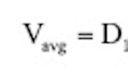
Fig.5 shows how STATESET is able to get the “inner loop” transfer function for a peak current controlled SMPS that uses the Middlebrook equation to define duty ratio. This intrinsic loop has previously not yet been studied. However, using GFT theory, a single injection loop cut was made (http://www.intusoft.com/lit/GFTSummary.pdf) just after the V avg signal. The resulting Bode plot exposes the high duty ratio instability of peak current control. Fig. 6 is the phase margin verses duty ratio resulting from the GFT analysis.
Solving for average current as a function of duty ratio yields:
Di is the initial duty ratio and is used to remove offset, centering the output at the controlled value. That's the value used for the STATESET initial condition.
The following average models that use STATESET are available from Intusoft for Buck, Boost and Buck/Boost(CCM):
- Peak current control
- Average current control
- Duty ratio control
The Buck, Boost and Peak Current Control models represent a new method to extend the voltage control model of Meares and Bello [2] from the CCM case, to the non-linear case where the controller can switch between CCM and DCM modes. Previously, the switching caused DC convergence failure in SPICE due to Middlebrook's equation having an implicit quadratic solution with two stable states. STATESET solves this problem by eliminating the need to solve the nonlinear equation during the DC operating point calculation.
USING STATESET WITH INITSWITCH
Fig.7 illustrates the use of the aforementioned new models to set up the operating point for a Buck regulator model. The model uses the Middlebrook equation to convert average current to duty ratio in a peak current controller. Without these elements, the DC operating point is unstable, precluding the AC analysis needed to predict stability margins. These elements were developed following Intusoft's study of digital control design and analysis using the IsSpice4 simulator. The new Z_DELAY element initialized its output, thus breaking the feedback loop in solution of the DC Operating point.
REFERENCES:
-
Middlebrook, R.D. “Modeling Current-Programmed Buck and Boost Regulators,” IEEE Transactions on Power Electronics,vol PE-4, 1989 pp. 36-52.
Download the story in pdf format here.
