Managing Distributed Power For Safety and Redundancy
Selecting the right solution to optimize the distribution of power to the connected loads is imperative for maximum system uptime. Switches, breakers, remote signals across Ethernet and automated switching between power sources are all important considerations.
With any electrical system, each component has a maximum energy capacity. Hardware failures can cause excessive load in that equipment and in the PDU, either of which can lead to several hazardous conditions including fire. A circuit protection device is used to detect an overload condition and automatically disengage the power source. These devices include a variety of fuses and circuit breakers designed to handle characteristics of various types of current load.
In some applications, particularly those with machinery connected to the PDU, an Emergency Power Off (EPO) may be required. An EPO is a large, prominently placed push button used to disconnect power to all circuits and thus all devices connected to the PDU. These buttons are intended to be easy to find and press in an emergency or “panic” scenario, such as when a person has identified a hazardous condition not automatically handled by the equipment itself.
Power Control for Redundancy
In applications where 100% power availability is critical, it is common to have two completely separate power sources. The loss of one power source would automatically result in the use of the other. Some equipment, such as computer servers, have the internal ability to connect to two sources and use either one. However, many types of equipment do not include this, and need an external device to do that switching for them.
An automatic transfer switch (ATS) provides this power control capability. The ATS circuit detects the loss of power on source A and switches to source B. Depending on the application, the switching can be performed by a mechanical relay, or may require a solid-state relay where a much faster transfer time is critical to prevent equipment shutdown.
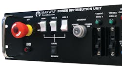
A common control requirement in a PDU (Fig. 1)
Fig. 1. This partial view of an application-specific PDU control panel shows an EPO button, circuit breakers, and circuit control switches.
is the switching on or off of power distribution branches. A branch, or circuit, is a subset of power outlets which share a common power source point within the PDU. These outlets may require separate on/off control as a group without affecting other circuits in the PDU. A simple switch or circuit breaker can provide that separation of control. This is typically a convenience feature to provide power to specific branches or circuits when needed, perhaps to enable a shutdown of related equipment for maintenance.
Switching of power at individual outlets is also a common feature whether for a select few outlets, or for every outlet in the PDU. Options include a dedicated breaker or mechanical switch on the PDU, or an electrical relay driven by a remote switch or by remote software signals across an Ethernet network.
The combination of circuit and outlet switching can be designed to optimize fixed workflow or procedure requirements, or maximize general purpose flexibility.
Control Methods
We’ve looked at various purposes for including switching capabilities in a power distribution unit. Next, we’ll look at ways in which those switching features can be implemented to complement the control environment in which the PDU will be used.
Local control is where the switching device is housed in, or mounted directly on, the PDU. Circuit breakers will almost always be implemented locally on the PDU. They can be used to combine the functionality of circuit protection and manual switching at the main power input, circuit branches, or even outlets. Some industries or safety policies may not allow circuit breakers to be used as switches as frequent toggling can degrade their performance.
Switches of push button, toggle, or rocker types mounted on the PDU can be used to control power on and off. This can be done directly on low-current power lines, or indirectly with high current power lines.
With direct power switching, the power line being controlled is routed directly through the switch providing the on/off control. This is common for most DC power sources, and for AC power sources of 120 volts or less and currents up to 15 amps.
Indirect power switching is used for higher voltages or currents to keep the power line off the control panel. The power line is wired through a mechanical relay, contactor, or solid state relay. A separate, low-power signal is run through the control switch to activate the power relay. The switch may be local, remote, or even another relay connected to a digital controller. Regardless of the exact hardware involved, the control switch is separated from the power relay to indirectly connect and disconnect power to the outlet(s).
Remote Control
Remote control is when the switching device is not located on the PDU itself, but rather a signal is sent to the PDU from a control panel on another piece of equipment. Remote signals will use indirect switching of power, and can be implemented several ways.
Fig. 2. With a dry contact, the control signal originates in and returns to the PDU. The remote panel provides only the switch.
A dry contact (Fig. 2) is technologically the simplest and most reliable form of remote control interface. A switch or relay at the remote station is used to communicate an on or off condition to the PDU. This is most commonly used for safety signals such as an EPO, but can also be used for conveying basic control commands as well.
Fig. 3. A discrete signal originates in and returns to the remote panel. How that signal can be used must be coordinated with the hardware in the PDU. The above circuit would be suitable for a voltage type of signal.
A discrete signal (Fig. 3) involves sending a fixed voltage or current signal which has only two states, such as 0 VDC vs. 5 VDC or 0 mA vs. 20 mA, from the remote panel to the PDU. The signal is received by a digital control circuit or the coil of a relay. The design requirements of the sender and receiver must be understood to ensure the signal is compatible with both. This type of signal is usually used for command signals to power on or off control circuits, and rarely for EPO circuits.
An analog signal is a variable voltage or current, typically 0–10 VDC or 4–20 mA, used to represent a data value such as line voltage, main input current, or chassis temperature.Though not common in PDU applications, analog signals can be used for unique integration requirements.
A communications interface provides a means to transmit multiple commands and data parameters using programmed digital controllers. The PDU will house a controller, and the remote station will house its own controller. Commands and data are exchanged using pre-defined “messages” between controllers following a standardized protocol such as RS-232, Modbus, HTTP, SNMP, or others. This form of remote communications offers the richest flexibility of control, but may require the most engineering resources to implement.
Automated Control
Automated control involves combining control devices to automate certain power switching behaviors or responses to measured or changing conditions.
Sequencing can be implemented to switch PDU outputs on or off in a specified order or at specified intervals. Some electrical equipment will draw a high amount of current for a very short time when started up. If numerous systems connected to the PDU are turned on all at once, the combined surge, known as inrush current, can trip the PDU’s circuit breaker. A digital controller can be used to switch outlets on with a slight delay between each one to avoid a large inrush. Sequencing can also be used if equipment connected to the PDU needs to be powered up in a specific order.
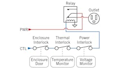
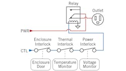
Fig. 4. Interlocks can be used to interrupt power for safety or environmental purposes, or even to prioritize the availability of power to specific outlets.
An interlock (Fig. 4) is a switch connected to a sensor. When the sensor state changes, the switch can be ctivated to turn power on or off. Various interlocks can be used to automate responses in various power or environmental conditions.
Power interlocks can be used to automate the power shutdown to a device which is sensitive to specific power signal conditions such as under or over voltage, phase rotation, or other parameters.
Environment interlocks can be used to power off connected equipment if changes to the installation environment warrants it. A thermal switch inside the PDU can be used so that its internal temperature can be monitored in harsh environments. If the temperature is too high, all power, or prioritized outlets, can be disabled to reduce thermal generation. Remote thermal switches can be used to react to surrounding or internal temperatures of equipment connected to the PDU. In this scenario, the sensor would be remotely located with the connected equipment, but the signal would be used by the PDU to disable corresponding outlets.
Other environment interlocks can also be integrated such as cabinet door sensors, airflow sensors, and water sensors. Again, either centrally located sensors at the PDU installation point, or remote sensors at connected equipment sites can be used.
PDU Integration advantages
Ultimately, a reduction in packaging complexity and component redundancy is the root of the following advantages found in the integration of power control features into a PDU:
• Reduced space
• Reduced weight
• Reduced cost
• Improved cable management
• Added convenience
When creating an integrated solution, one needs to address the unique needs of an application, and optimize the selection of components for power capacity and packaging efficiency. A single-chassis integration of these capabilities to reduce space, weight, and costs, and to improve control capabilities has distinct advantages compared to separately housed third-party components. Ultimately it’s the combination of power performance, packaging efficiency, and product quality to meet specific power distribution needs.


