Digital Control Provides LLC Performance Enhancements
It is well known that high efficiency and high performance power delivery are important to both the power supply design house as well as the end users of these power supplies. In some cases, the total efficiency of the power supply is required to be 96% (Table 1), while simultaneously maintaining a high power factor and low total harmonic distortion [1]. Requirements like these are putting significant pressure on the DC/DC stage to deliver efficiency exceeding 96%.
Resonant LLC converters are gaining significant attention due to their ability to achieve these high efficiencies. Unfortunately, the implementations of many traditional high-performance features are less understood for this topology, and in many cases difficult to implement. Some classic examples include constant current operation, constant power operation, monotonic start-up, and light-load regulation.
TI’s Power Seminar, “Designing an LLC Resonant Half-Bridge Power Converter,”[2] provides a detailed overview of many of these features. It also addresses a technique utilizing frequency modulation (FM) and pulse-width modulation (PWM) mode switching as an effective counter measure. While this solution is very effective, it is so, at the cost of efficiency during several operating conditions. These additional losses arise from the loss of zero voltage switching (ZVS) that occurs during PWM mode.
A novel way of meeting these features without the loss of ZVS involves dynamically changing from FM control to phase-shift modulation control (PSM). This solution is achieved through the use of a programmable digital controller (UCD3138) that has the ability to utilize multiple modulation techniques based on system demands [3].
PWM and FM mode
Fig. 1 shows a classic full-bridge LLC converter. It is well known that the primary method used to regulate this circuit’s output voltage is FM. This works by utilizing the variable frequency nature of the reactive components on the primary side to subsequently limit the energy delivered to the secondary. While FM can be made to work very well for a wide range of operating conditions, problems can arise during start-up, light load, and short circuit operation.
TI’s Power Seminar, Designing an LLC Resonant Half-Bridge Power Converter,[2] discusses how to leverage the flexible and programmable nature of a digital controller to implement dynamic mode switching between PWM and FM to achieve these features.
While this method works well, it produces two negative side effects. First, and most significant, the system loses ZVS. Since this topology is principally chosen for its efficiency benefits, this penalty can be very problematic to meeting the end system efficiency requirements. Second, when the converter first enters PWM mode it actually loses control of the output voltage. This loss of control exhibits itself as a small dead zone in the control algorithm. In most cases a properly tuned feedback scheme can address this, however, it can also produce troublesome voltage glitches.
To illustrate these behaviors consider the current ILR(t), flowing in the direction illustrated in Fig. 1. This condition is possible if Q1 and Q4 are on, or if the body diodes of Q2 and Q3 are on. For the sake of argument, consider the initial condition that Q1 and Q4 are on. If they are then turned off, the current is forced to flow through the body diodes of Q2 and Q3. This forces the voltage at the drain-source junctions to simply transition to the opposite voltage rail. The voltage stays there as long as the current continues to flow in the direction shown. Because of this, only the phase of the volt-seconds applied to the resonant tank changes. It does nothing to limit the energy flow to the secondary. Therefore, if ZVS is maintained when the MOSFETs are turned off, nothing has been accomplished to improve the converters ability to control the output voltage.
However, if ZVS is lost, something different happens. Specifically, the voltage at the MOSFET drain-source junctions now can become the same value on the drain of Q2 as it is on the drain of Q4. This means that the voltage presented to the resonant tank is now zero. This can dramatically change the energy flow from primary to secondary. While this nicely solves one problem, unfortunately it creates another. Since neither drain is likely to be at ground or VIN, both MOSFETs now turn on with switching losses.
PSM and FM mode
As an alternative to changing from FM to PWM, PSM can accomplish a similar result while at the same time improving the monotonicity of the control to output transfer function and improving the power supply efficiency. This again is a great candidate for digital control, since it is beneficial to be able to have a wide degree of flexibility on the mode switching boundary conditions, as well as well-timed consistent and repeatable results.
While it was necessary for the control to lose ZVS before PWM operation could begin to regulate the output, this constraint is not necessary for PSM – allowing the controller to immediately impact the output voltage while simultaneously maintaining ZVS for a much wider range of operating conditions. Fig. 2 shows an example of one of these ZVS transitions.
The image on the left side of the Fig. 2 shows the case where Q1 and Q4 are both on with the resonant tank current flowing through the channels of the respective MOSFETs. If Q4 turns off, the current that was flowing through Q4’s MOSFET channel is now diverted to flow through the body diode of Q3. Therefore, Q3 is free to turn on under ZVS. Additionally, during the time period when Q1 and Q3 are on (or Q3’s respective body diode), there are zero volts presented to the resonant tank. This immediately changes the energy flow from the primary to secondary, improving the regulation control for this mode. Fig. 3 illustrates the mechanism of this enhanced control.
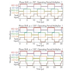
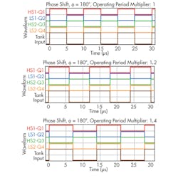
Notice that when the phase (f) of the control effort is 0° the voltage applied to the resonant tank is zero. However, when f takes on larger values, the volt-seconds applied to the resonant tank increases proportionally. This in-turn has a direct impact on the subsequent energy delivered to the load.
Fig. 3 also illustrates the natural mode switching that occurs at the f= 180° operating point. Once this phase-shift is achieved, the control effort transitions from modulating the phase to modulating the frequency. This natural handoff makes the control to output transfer function predictable, monotonic and smooth.
Fig. 4 shows the measured efficiency improvement from using PSM versus PWM. Since both converters operate with FM control at heavy loads, differences are only observed at light loads. However, if constant current operation is important, PWM operation can cause significant issues due to the lower operating voltage and the subsequent loss of ZVS during a heavily loaded operating point.
References
1. Plug and Play website, “80 PLUS Certified Power Supplies and Manufacturers
2. Brent McDonald, Dave Freeman, “Designing an LLC Resonant Half-Bridge Power Converter,” SEM2000, Texas Instruments 2012
3. Download a datasheet for the UCD3138: http://www.ti.com/product/ucd3138
4. Huang, Hong, “Designing an LLC Resonant Half-Bridge Power Converter,” SEM1900, Texas Instruments 2010


