Special DC/AC Inverter Avoids Transformer Core Saturation
Topology that is result of the project provides a possibility of achieving maximum physically attainable level of energy that can be received from a ferromagnetic transformer. Specified inverter is also a kernel for DC-DC converters design. The work that was done confirms high effectiveness of the project and we submitted application for patent [3].
Related Articles
- Performance of Silicon Carbide Diodes in Solar Micro-Inverters
- New Topology Cuts Size, Improves Performance Of PV Inverters
- Inverter/Charger Supports Grid-Interactive and Off-Grid Applications
- How to Run a Split-Phase Induction Motor with a Three-Phase Inverter
- Partitioning Eases Implementation Of Three-Level IGBT Inverters
- IGBTs For Three-Level Inverters Can Meet Energy-Efficient Design Needs
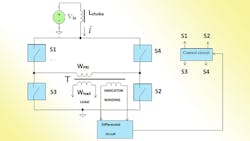
Fig. 1 shows a block diagram illustrating an example of the bridge topology. When direct current voltage source Vin is connected to inverter, the control circuit closes switch S1 and switch S2, while keeping switch S3 and switch S4 open at this time. Magnetizing current iµ in primary winding Wpri of transformer T (transformer T core is chosen to have no air gap) begins to increase linearly (Fig. 3c, graph 3.9). Because input choke LCHOKE, and primary winding are connected in series, voltage on primary winding WPRI equals:
where:
UWPRI = Voltage across primary winding
VIN = Voltage of direct current voltage source
LCHOKE = Inductance value of input choke (because input choke is chosen with a gapped core, Lchoke is practically constant)
i = Current passing through input choke LCHOKE and primary winding WPRI of transformer T
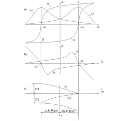
When magnetizing current iμ in primary winding WPRI of transformer T reaches a value corresponding to coercive force “+Hc ” (Fig. 3a), the differential permeability of the core of transformer reaches its maximum value:
[Fig. 3a, graph 3.3 (Stoletov’s curve)]. Magnetizing current at this point equals:
where:
Wpri = Number of turns in primary winding
ℓ = Average length of magnetic path in the core
When secondary winding WLOAD of transformer T is connected to a load, flux created by the load current, according to the Lenz law, is compensated by a corresponding flux increment that is created by the current in primary winding, thus in a steady state condition in the core of the transformer only the flux created by the magnetizing current iμ is in effect. The maximum value of the mutual inductance MMAX, between primary winding and secondary winding, which defines the working flux in the transformer core:
where:
μ₀ = Permeability of a vacuum
S = Cross-section area of the transformer core
WLOAD = Number of the turns in secondary winding
The maximum value of the mutual inductance, MMAX, corresponds to the maximums on Stoletov’s curves (Fig. 3a, graph 3.3 and 3.4). That is why the averaged mutual inductance MAVE corresponding to the process of reversal of the magnetization of the core of transformer between points “-Hc” and “+Hc” (Fig. 3a) reaches its maximum too. Furthermore, power, P, that transfers into the load reaches its maximum as well with any current in the load (between its minimum and maximum values):
where:
ILOAD = Load current
f = Frequency of the reversal of the magnetization of the transformer core
Magnetizing losses that are defined by the area “(+Hc) - (e) - (-Hc) - (g) - (+Hc)” (Fig. 3a) inside the hysteresis loop under the circumstances reach their minimum. When magnetizing current in primary winding is slightly above the value defined by Equation 3, the magnetic field strength in the core of transformer is slightly above “+Hc”. The voltage across choke, defined as (LCHOKE) di/dt is slightly elevated. The voltage across primary winding is slightly reduced (Equation 1). The voltage across indicator winding is decreasing and the voltage at the output of differential circuit changes its sign (Fig. 3b, graph 3.5 below point 3.8). At that moment control circuit opens switch S1 and switch S2, subsequently closing switch S4 and switch S3, resulting in the magnetizing process going in direction from point “+Hc” to the point “-Hc” (Fig. 3a, subsiding part 3.1 of the hysteresis loop). Magnetizing current in the primary winding decreases (Fig. 3-c, line 3.10). Differential permeability of the core of transformer changes (Fig. 3a, Stoletov’s curve line 3.4). At point “-Hc” (Fig. 3a), differential permeability reaches its maximum. When the absolute value of the magnetizing current is slightly more than:
The absolute value of the magnetic field strength is slightly more than modulus |-Hc |, the voltage across choke is slightly elevated, and the voltage across primary winding is slightly reduced (Equation 1). The voltage across indicator winding is decreasing and the voltage at the output of differential circuit changes its sign (Fig. 3b , graph 3.6 above point 3.7). At that moment control circuit opens switch S4 and switch S3, subsequently closing switch S1 and switch S2, resulting in the magnetizing process going in direction from point “-Hc” to the point “+Hc” (Fig. 3a, rising part 3.2 of the hysteresis loop). And so on. In the present topology, when the temperature of the core of transformer is increasing and saturation flux density is decreasing, area “(+Hc) - (e) - (-Hc) - (g) -(+Hc)” (Fig. 3a) is also decreasing leading to decreased magnetizing losses. According to the Faraday’s law:
where:
T = Period of the reversal of core magnetization:
ΔΒ is the increment of the flux density corresponding to the increment of coercive force from “-Hc” to “+Hc”, therefore:
From Equation 8 and Equation 9 it follows that frequency, f, equals:
This is defined by the value of μMAX. That is to say, for the present topology, magnetizing frequency and, therefore, magnetizing losses approach their minimum. The present topology provides a possibility of achieving maximum physically attainable level of energy that can be received from a ferromagnetic transformer.
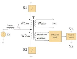
Referring now to Fig. 2, the block diagram illustrates an embodiment of the pull-pull topology. When direct current voltage source (Vin) is connected to DC-AC inverter, control circuit operates to close switch S1, while keeping switch S2 open. Magnetizing current iμ in primary winding W1pri of transformer T (transformer core is chosen to have no air gap), begins increasing linearly (Fig. 4c, graph 4.9). Because input choke Lchoke and first primary winding W1pri or second primary winding W2pri (depending on positions of switches S1 and S2) are connected in series, voltage on the primary winding equals:
where:
UWPRI = Voltage across first primary winding ,W1pri, when switch S1 is closed and switch S2 is open, or voltage across second primary winding W2pri, when switch S1 is open and switch S2 is closed
VIN = Voltage of direct current voltage source
LCHOKE = Inductance of the input choke (input choke is chosen with a gapped core, therefore LCHOKE is practically constant)
i = Current passing through in series connected input choke and primary windings W1pri of transformer, when switch S1 is closed and switch S2 is open, and in series connected input choke and primary winding W2pri, when switch S2 is closed and switch S1 is open.
When magnetizing current iμ in primary winding W1pri reaches the value corresponding to coercive force “+Hc” (Fig. 4a), the differential permeability of the core of transformer reaches its maximum:
(Fig. 4a, Stoletov’s curve - graph 4.3). At this point magnetizing current equals:
where:
ℓ = Average length of the magnetic path in the core of transformer
WPRI = Number of the turns in first primary winding W1pri or second primary winding W2pri
When a load is connected to secondary winding of transformer , flux created by the current in the load, according to the Lenz law, is compensated by a corresponding flux increment that is created by the current in first primary winding W1pri (or second primary winding W2pri) and, under steady state conditions in the core of transformer operates only the flux created by the magnetizing current iμ. The maximum value of the mutual inductance MMAX between first primary winding W1pri (or second primary winding W2pri) and secondary WLOAD, which defines the operating flux in the transformer core:
where:
S = Cross-section area of the core of transformer
WLOAD = Number of turns in secondary winding
The above value of mutual inductance corresponds to the process of the reversal of the magnetization of the core of transformer between points “–Hc” and “+Hc” (Fig. 4a) has its maximum as well. Furthermore, the power (P) which is transferred to the load also reaches a maximum under any current in the load, between minimum to maximum values:
where:
Iload = Load current
f = Frequency of the reversal of the magnetization of the transformer core
Under the above conditions, magnetizing losses that are defined by the area “(+Hc) - (e) - (-Hc) - (g) - (+Hc)” inside of the hysteresis loop (Fig. 4a) reach their minimum. When the magnetizing current in first primary winding, W1pri, is slightly above the value defined by Equation 3.1, the magnetic field strength in the core of transformer is slightly above “+Hc”. The voltage across choke (LCHOKE di/dt) is slightly elevated at this moment, and the voltage across first primary winding, W1pri, is slightly reduced (Equation 1.1).
The voltage across indicator winding at that moment is decreasing, and at the output of differential circuit the voltage changes its sign (Fig. 4b, graph 4.5 below point 4.8). At that moment control circuit opens switch S1 and closes switch S2, leading the magnetizing process to proceed in the direction from point “+Hc” to the point “-Hc” along subsiding portion 4.1 of the hysteresis loop (Fig. 4a). Magnetizing current in primary winding W2pri then increases (Fig. 4c, line 4.10). Differential permeability of the core of transformer , is changing along line 4.4 (Fig. 4a, Stoletov’s curve). At point “-Hc” (Fig. 4a) differential permeability reaches its maximum. When the absolute value of the magnetizing current is slightly above the value of:
The absolute value of the magnetic field strength is slightly above the modulus |-Hc| and the voltage across choke (LCHOKE di/dt) is slightly elevated, the value of the voltage across second primary winding W2pri is slightly reduced (Equation 1.1). The voltage across indicator winding at that moment is decreasing and the voltage at the output of differential circuit changes its sign (Fig. 4-b, line 4.6 above point 4.7). At that moment control circuit opens switch S2 and closes switch S1, leading the magnetizing process (Fig. 4c, line 4.10) to proceed in the direction from point “-Hc” to the point “+Hc” along the rising portion 4.2 of the hysteresis loop (Fig. 4a). And so on. This push-pull topology offers similar advantages to the bridge topology described in reference to Fig. 1.
Making use of the described topology gives possibility to reduce size of the core of the trans-former and quantity of turns in the windings herewith frequency of the switching reaches its minimum for the given design. This circumstance allows to reduce losses in switches and transformer and as a result to increase efficiency up to level 90 percent and higher. The proposed topology also works very steadily in wide range of input voltage.
References
[1] Pressman A. I., “Switching Power Supply Design.” McGraw-Hill, ISBN 0-07-052236-7.
[2] Hnatek, E. R. “Design of solid-state power supplies.” Van Nostrand Reinhold Company, ISBN 0-442-23429-5.
[3] US Provisional Patent Application S/N 61/864, 561.


