380 VDC Input Supplies Enable Data Centers to Use HVDC Power Distribution
Vicor’s Gary Gill says that using high-voltage DC for power distribution offers tangible and significant benefits for both sourcing options and system end-to-end performance. New technical developments in components and devices, along with additional power-system objectives, are acting as catalysts to make DC-based systems a better and available alternative. These developments include innovative conversion, control, and distribution approaches, much of which is enabled by advanced semiconductors and conversion topologies that function effectively in ways not previously possible. As a result, high-voltage DC (HVDC) systems are now practical for distribution and use within a building, office park, warehouse, school, and factory.
Related Articles
- Assessing Point-Of-Load Regulators Using Non-Invasive Techniques
- Bus Converters Push Power Levels Higher
- Assessing Point-Of-Load Regulators Using Non-Invasive Techniques
- Distributed Power Architectures Evolve and Reconfigure
- Power Management Basics: Power Supply Fundamentals
- Power Management Basics: Power Supply Characteristics
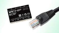
To support the trend to HVDC power distribution recently unveiled its first module utilizing the Converter housed in Package (ChiP) power component platform. The new ChiP bus converter modules (BCM®) supply 1.2 kW at 48 V with 98% peak efficiency and 1880 W/in3 power density. The resulting performance is 4 x the density of competing solutions, enabling efficient, high voltage DC distribution infrastructure in datacenter, telecom, and industrial applications.
With a nominal input voltage of 380 V and a K-factor of 1/8, Vicor’s ChiP BCM fixed-ratio power converters supply an isolated 48V distribution bus with a peak efficiency of 98%. With its input range of 260 to 410 V, the new BCM supports outputs ranging from 32.5 V to 51.25 V. BCMs are based on Vicor’s ZCS/ZVS Sine Amplitude Converter™ topology and operate at a 1.25 MHz switching frequency, providing fast response time and low noise operation.
ChiP Platform
Vicor’s ChiP platform sets the standard for a new generation of scalable power modules. Leveraging advanced magnetic structures integrated within high density interconnect (HDI) substrates with power semiconductors and control ASICs, ChiPs provide superior thermal management supporting unprecedented power density. Thermally-adept ChiPs enable users to achieve low cost power system solutions with previously unattainable system size, weight and efficiency attributes, quickly and predictably. The advent of ChiPs embodies a modular power system design methodology enabling designers to achieve high performance, cost-effective power systems from AC or DC sources to the Point of Load using proven building blocks.
Offered in the 6123 ChiP package, the new 380 VDC VI Chip BCMs measure 63 mm by 23 mm, with a height of only 7.3 mm. Initially offered as a through-hole device, package options will also include SMD variants. ChiP BCMs may be paralleled to provide multi-kW arrays and are capable of bi-directional operation to support battery backup and renewable energy applications. Standard BCM features include under-over-voltage lockout, over-current, short circuit and over-temperature protection. ChiP BCMs incorporate digital telemetry and control features that can be configured to meet customer requirements.
Vicor’s Gill points to several reasons for the move to HVDC power distribution:
- DC does not require source synchronization as AC does.
- DC can draw upon wind, solar, and the grid as each source is available.
- There are no phase balancing or harmonic issues.
- No "stranded" equipment issues, all costly investments in infrastructure which may become obsolete or redundant.
- DC offers a lower total cost of ownership (TCO) in building wiring, copper, and connectors,
- DC provides an efficiency increase of between 8 and 10%.
- A properly configured DC system offers more potential for power extraction from multiple available sources.
Gill also pointed out benefits that are not be immediately apparent.
- Most backup-energy sources, such as batteries and flywheels, are inherently DC.
- Telecom and server loads run on DC.
- There are fewer intermediate, efficiency-robbing stages.
- DC-based approach exhibits greater reliability due to fewer potential points of failure.
In addition, the HVDC approach is not just a speculative dream or laboratory curiosity. It has industry-wide support from critical component vendors, of course. It is also supported by industry consortia which are developing essential standards and interoperability specifications, such as the DCG+C [DC Components and Grid] consortium, the ITU [International Telecommunications Union] via standard L.1200, ETSI [European Telecommunications Standards Institute] via EN 300 132-3-1, the IEC [International Electrotechnical Commission], NTT/Japan [Nippon Telegraph and Telephone], and the IEEE.
Existing Technology
Before looking at the topology and implementation of a 400 VDC distribution approach, first look at the existing approaches used for major power consumers such as data centers or telecom central offices. In the data center an incoming high-voltage AC line is stepped down, and then converted to DC so it can be paralleled with a battery-backup system (Fig. 1). The DC is then converted back to high-voltage AC for distribution within the building, then converted yet again from AC down to lower-voltage DC, and then to voltages for the circuitry rails via DC-DC converters. Thus, there are four major conversion stages from incoming AC to final DC.
For the existing telecom system, there are just two major stages but with major points of inefficiency (Fig. 2). The line AC is converted to 48 VDC and combined with the backup batteries; this 48 VDC line then supplies an array of DC-DC converters which provide the local, low-voltage rails needed for the circuitry.
The HVDC system also has just two major conversion stages, but there is more to the end-to-end performance metric than the number of stages alone, as the efficiency of each stage is also critical. In the HVDC approach, the stages are both more efficient and more reliable.
HVDC topology begins with the line AC rectified to 380 VDC (nominal), with the battery backup also operating at that voltage (Fig. 3). The DC voltage is then distributed throughout the facility and stepped down by local DC-DC converters to supply the rails of the processor and various loads. The system can draw on the outside AC line, batteries, and even onsite renewable sources such as wind and solar simultaneously or individually, in case there is a failure (such as grid problems due to a storm).
Getting Down to Single Volts
The reality is that most circuitry operates from DC voltages below 12 V, and even down to the 1V region. The challenge for any distribution/conversion system is to develop and deliver those low voltages (and their high currents) efficiently and reliably.
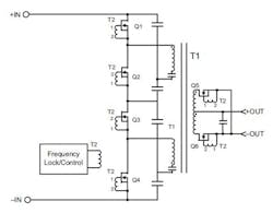
HVDC can meet this requirement, as well, using several available building blocks. One is a Sine Amplitude Converter used in the form of a BCM®Bus Converter, which is an isolated, non-regulated DC-DC converter which uses a Zero-Voltage/Zero-Current Switching architecture (Fig. 4). The SAC is like a traditional AC transformer except that it is DC input/output, and has an input/output voltage ratio that is fixed by design. For example, with a transformer ratio (K) of 1/8, it produces a 50 VDC output from a 400 VDC input, and 47.5 V from a 380 V input.
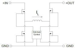
The SAC reaches over 96% efficiency partially due to its fixed, high frequency (>1 MHz), soft-switching topology. The result is a power density of 70 W/cm3 ; a Vicor full-chip bus converter measuring just 3.25 x 2.2 x 0.67 cm (1.28 x 0.87 x 2.265 in.) comparable to a standard RJ-45 Ethernet plug can deliver up to 330 W (Fig. 5). The second block is the non-isolated buck-boost regulator, also using Zero-Voltage Switching and 1 MHz operation, , resulting in small size and high efficiency of 97% (Fig. 6).
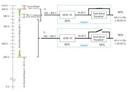
Working together, the SAC/BCM and buck-boost regulator provide an equalizer (adapter) function over the full span of input voltages for the normal service range as defined by ETSI (Fig. 7). At the normal 380 V point, the bus converter can drop the line down to 48 V, with the equalizer operating in a power-through mode (with a bypassed buck-boost). Thus, system efficiency is enhanced because the unit converts only when needed. If the DC voltage from the line or battery drops towards 260 V, the buck-boost converter "kicks in" and maintains the fixed 48 V rail.
In either case, the architecture maintains high efficiency and allows for seamless, dynamic use of multiple sources-- a rectified DC line, battery, and renewables as they become available.
About the Author

Sam Davis
Sam Davis was the editor-in-chief of Power Electronics Technology magazine and website that is now part of Electronic Design. He has 18 years experience in electronic engineering design and management, six years in public relations and 25 years as a trade press editor. He holds a BSEE from Case-Western Reserve University, and did graduate work at the same school and UCLA. Sam was the editor for PCIM, the predecessor to Power Electronics Technology, from 1984 to 2004. His engineering experience includes circuit and system design for Litton Systems, Bunker-Ramo, Rocketdyne, and Clevite Corporation.. Design tasks included analog circuits, display systems, power supplies, underwater ordnance systems, and test systems. He also served as a program manager for a Litton Systems Navy program.
Sam is the author of Computer Data Displays, a book published by Prentice-Hall in the U.S. and Japan in 1969. He is also a recipient of the Jesse Neal Award for trade press editorial excellence, and has one patent for naval ship construction that simplifies electronic system integration.
You can also check out his Power Electronics blog.
