This Week in PowerBites: AI Power Conversion, NASA's Electric X-Plane
This article is part of the Power Management Series: This Week in PowerBites
200-kW Inverter Uses AI to Achieve 99+% Efficiency at 100 kHz
This video provides an overview of how Pre-Switch's soft-switching technology works, and how it can reduce several types of losses commonly found in today's EVs.
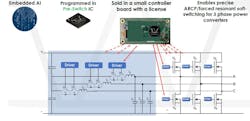
Can artificial intelligence (AI) enhance the efficiency of motor drivers, inverters, and other power-conversion applications? Pre-Switch Inc. is betting on it. The company recently demonstrated the world’s-first AI-based dc-ac, ac-dc soft-switching controller. The controller was demonstrated in the CleanWave200, a 200-kW (space vector modulated) evaluation inverter that uses three discrete, low-cost 35-mΩ SiC MOSFETs per switch location.
The controller includes logic that embodies several advanced self-learning algorithms, allowing it to optimize the shape and timing of each switching pulse. This results in documented efficiencies that exceed 99.3% at 100 kHz.
A block diagram of the CleanWave200 reference design.
Bruce Renouard, Pre-Switch CEO, explains that "the Pre-Switch controller IC analyzes multiple inputs on a cycle-by-cycle basis, making adjustments in real-time to small, forced-resonant transistors, enabling perfect soft-switching in harsh changing environments. Variations in system temperature, device degradation, changing input voltages, and abrupt current swings are all accounted for and optimized within the Pre-Switch AI algorithm. "This enables many applications to produce an almost pure sine wave output,” he says, “while running at to four to ten times the switching frequency of a conventional circuit.”
Renouard notes that the cleaner output and higher switching speeds made possible by the controller's self-learning algorithms yield the high conversion efficiencies, which, in turn, enable designers to create more compact applications that require fewer, smaller passive components and heatsinks. Key applications include electric vehicles, solar inverters, wind turbines, UPS, storage, and motor drives.
The CEO also says that when used in EVs, the AI-enabled inverter's high efficiency and reduced motor losses at the lower torque outputs typically used by motorists can add up to 12% to the vehicle's range.
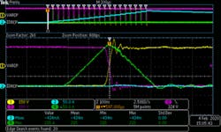
This is a snapshot of a live demonstration of the CleanWave200 evaluation system, illustrating the Pre-Switch controller's AI actively learning during initial startup. It begins with unknown starting conditions and ultimately optimizes the timing and other adjustments necessary to ensure that a pulse-width-modulated (PWM) input generates a current ramp to simulate the first part of a sine-wave output. Click here to see the animated demonstration and get a more detailed explanation of how the Pre-Switch controller works.
To assist design engineers in evaluating the new technology, Pre-Switch has published data plots of the evaluation inverter's system efficiency at multiple switching speeds between 50 and 100 kHz, with multiple input voltages, power and current outputs.
The Cleanwave200 evaluation system, reference design, and design files can be ordered from Pre-Switch.
Co-Packaged 650-V GaN Transistors Optimized for Power-Conversion Apps Up to 200 W
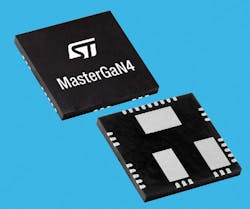
STMicroelectronics’ MasterGaN4 power packages integrate two symmetrical 650-V gallium-nitride (GaN) power transistors with 225-mΩ RDS(on), alongside optimized gate drivers and circuit protection. The configuration helps simplify the design of high-efficiency power-conversion applications up to 200 W.
The MasterGaN4 facilitates design using wide-bandgap GaN power semiconductors by taking away the complex gate-control and circuit-layout challenges. With inputs tolerant of voltages from 3.3 to 15 V, MasterGaN4 can be controlled by connecting the packages directly to Hall-effect sensors or a CMOS device such as a microcontroller, DSP, or FPGA.
Leveraging the higher operating frequencies enabled by the superior switching performance of GaN transistors, as well as their increased efficiency that reduces thermal dissipation, designers can choose small magnetic components and heatsinks to build more compact and lightweight power supplies, chargers, and adapters. MasterGaN4 is well-suited for use in symmetrical half-bridge topologies as well as soft-switching topologies like active clamp flyback and active clamp forward.
The wide 4.75- to 9.5-V supply-voltage range allows for convenient connection to an existing power rail. Built-in protection further simplifies design, including gate-driver interlocks, low- and high-side undervoltage lockout (UVLO), and overtemperature protection. There’s also a dedicated shutdown pin.
As part of the launch, ST is introducing a dedicated prototype board (EVALMASTERGAN4) that provides a complete set of features to drive the MasterGaN4 with a single or complementary driving signal. An adjustable deadtime generator is provided as well. The board gives users the flexibility to apply a separate input signal or PWM signal, insert an external bootstrap diode, separate the logic and gate-driver supply rails, and use a low-side shunt resistor for peak-current-mode topologies.
MasterGaN4 is in production now, in a 9- × 9- × 1-mm GQFN package that has over 2-mm creepage distance for safe use in high-voltage applications. Pricing starts at $5.99 for orders of 1000 pieces. The EVALMASTERGAN4 board costs $87.00.
For additional information, visit www.st.com/gatedrivers.
Compact High-Current Inductors Feature Low Losses
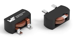
The 2010 high-current inductor is the latest addition to Würth Elektronik's WE-HCF-SMT family of high-current inductors. The device offers several improvements in its internal design that enable higher current densities and lower losses.
The magnetically shielded flat wire coil with MnZn core impresses with a low resistance of 0.84 mΩ and low core losses. The recommended three-pin contacting ensures mechanical stability of the WE-HCF, which is designed for an operating temperature of −40 to +125°C. Potential applications include POL regulators for FPGAs, ASICs, and GPUs; high-efficiency dc-dc converters; high-current switching power supplies; forward converters; half-bridge and full-bridge converters; as well as battery chargers and solar inverters.
WE-HCF 2010 is available immediately from stock with no minimum order quantity. Würth Elektronik will provide free samples to developers upon request. Visit the link above for specifications and pricing information.
PFC IC Delivers 98% Full-Load Efficiency for Consumer and Industrial Apps
The HiperPFS-4 power-factor-correction (PFC) controller IC from Power Integrations comes with an integrated Qspeed low reverse-recovery charge (Qrr) boost diode. This combination delivers greater than 98% full-load efficiency in consumer and industrial applications between 75 and 400 W.
Designs using HiperPFS-4 ICs are able to deliver very high efficiency across their entire load range with as little as 36 mW of no-load power consumption at 230 V ac. Able to achieve a power factor of greater than 0.95 at above 20% load, it’s well-suited to applications such as PCs and TVs, as well as battery chargers, power tools, industrial power supplies, and LED lighting.
The HiperPFS-4 IC combines a continuous-conduction-mode (CCM) PFC control circuit, a boost diode, and a 600-V MOSFET in a single package. Co-packaging the boost diode eliminates a separate heatsink mount, leading to a simpler design and better thermal performance. In addition, the built-in Qspeed diode minimizes parasitic trace inductances, which provides greater robustness against ac-line surges, which in turn reduces voltage spikes seen by the power switch during transients by up to 50 V. The integrated 600-V MOSFET is therefore easily able to meet the 80% derating requirement when delivering a 385-V dc constant-voltage bus.
The HiperPFS-4 IC packaged with the QSpeed boost diode is available now in volume product quantities. Devices are priced starting at $1.56 in quantities of 10,000. For more details, contact a Power Integrations sales representative or one of the company’s authorized worldwide distributors: Digi-Key, Farnell, Mouser, and RS Components.
Reference Design Simplifies 30-W Wireless Charging, Power Sharing for Mid-Tier Smartphones
A new reference design developed by Renesas Electronics enables cost-effective 30-W wireless-charging capabilities for mid-range smartphones powered by Qualcomm's Snapdragon 780G 5G Mobile Platform. This brings the same high-power wireless-charging capabilities that the company’s earlier reference design currently provides for flagship devices to a much larger market.
The design is based on Renesas' P9412 wireless power receiver, the industry’s first 30-W power receiver. With a high-voltage integrated capacitor divider, it offers end-to-end efficiency of over 85% and a 40% reduction in solution size compared with conventional solutions.
To ensure a safe and fast charging experience, the device firmware includes a custom high-power protocol that allows the system to authenticate any power transfer above the 15-W safety limit defined by the Wireless Power Consortium’s (WPC) Extended Power Profile (EPP) standard. Renesas’ Wattshare technology also enables the mobile device to become a power source and wirelessly charge accessories in the ecosystem, such as earbuds and smart watches. The new reference design is available now. For more information on the reference designs, visit renesas.com/P9412.
AEC-Q200-Compliant, Sulfur-Resistant Thick-Film Resistor Arrays Thrive in Tough Environs
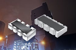
Bourns Inc. recently introduced several new families of AEC-Q200-compliant, surface-mount, thick-film chip resistor arrays intended to help designers conserve board space and reduce total solution cost. Offering long-life protection against many sulfurous environments, the Model CAYxxA-AS series are the first chip arrays from Bourns that meet both the AEC-Q200 standard and anti-sulfur protection requirements based on the ASTM-B-809-95 and EIA-977 (test parameter B) standards. As a result, they’re superior circuit-conditioning solutions for a wide range of transportation, consumer electronics, industrial automation, power supply, LED lighting, and communication base-station applications that must operate in extreme conditions.
These latest resistor families from Bourns are constructed using a thick-film element printed onto a ceramic substrate, which allows for a wide resistance range and increased design flexibility in terms of size and dimensions. The new AEC-Q200-compliant Model CATxxA-LF concave and CAYxxA-LF and CAYxxA-AS convex chip arrays come in 1- and 1.6-mm widths and contain two or four pieces of isolated thick-film resistive elements printed onto a single ceramic substrate.
The CATxxA-LF, CAYxxA-LF, and CAYxxA-AS series are available now and are RoHS compliant. For additional product information, visit www.bourns.com/products/resistors/chip-resistor-arrays.
Shocking News: NASA's Electric X-Plane One Step Closer to Flight
NASA's all-electric X-57 Maxwell aircraft goes through high-voltage ground testing at NASA's Armstrong Flight Research Center in California. A goal of the X-57 project is to help the FAA set certification standards for emerging electric-aircraft markets. (Credit: NASA Photo/Lauren Hughes)
NASA recently announced that the X-57 "Maxwell," the agency's first all-electric X-Plane, has begun the series of high-voltage ground tests that will clear it for the first phase of flight testing later this year. But with so many commercial electric aircraft startups like Joby, Bye Aero, Lilium, Eviation, and many others grabbing the headlines, you might well wonder why NASA is building its own experimental electric aircraft.
Like all of the legendary X-Planes that preceded it, the goal is not commercialization, but to gain a deeper understanding of the technical challenges designers and operators will face in this new frontier of flight. The X-57 Maxwell (named for the scientist, not the spy), under construction at NASA's Armstrong Flight Research Center in Edwards, Calif., will serve as a test bed for several technologies. NASA’s primary goal for X-57 is to share the electric-propulsion design, lessons learned, and airworthiness process with regulators, as new electric aircraft markets begin to emerge.
The X-57 is based on the Tecnam P2006T, a small, commercially produced twin-engine transport. The airframe is being modified in three phases, allowing each configuration to be thoroughly evaluated before the next set of modifications is introduced. In its final configuration, it will employ a new high-efficiency, high-aspect wing and replace the Tecnam's twin 100 HP ICE motors with a unique dual-mode propulsion system.
The X-57 is undergoing a series of phased modifications and subsequent tests, such as the test of its in-flight telemetry system, conducted in April 2020. (Credit: NASA/Ken Ulbrich)
The dual-mode propulsion will employ a pair of 60-kW electric motors mounted on the wingtips, which will sustain the aircraft after takeoff. These "cruise motors" will be supplemented by 12 smaller "high-lift" motors, with six embedded in each wing. The airflow they create over the wing will provide lift augmentation during takeoff and at low aircraft speeds.
When the X-57 enters cruise mode, the two larger wingtip motors will sustain flight while the in-wing motors deactivate and their propeller blades fold inward to reduce drag. During landing, the smaller high-lift motors will reactivate to enhance the Maxwell's lift and handling characteristics while operating at the slower speeds required for approach and landing.
This artist’s concept image shows NASA’s first all-electric X-plane, the X-57 Maxwell, in its final configuration, flying in cruise mode over NASA’s Armstrong Flight Research Center in Edwards, Calif. In Mod IV test flights, X-57’s high-lift motors will deactivate and fold their props during cruise mode. (Credit: NASA Langley/Advanced Concepts Lab, AMA Inc.)
Once the final configuration is fully tested, NASA expects this modestly funded program will provide valuable information on the unique operational characteristics, stresses, and maintenance requirements that the Federal Aviation Authority (FAA) will need to have to create safe, practical requirements for the certification and operation of commercial electric aircraft.
The project is also using several “design drivers” (NASA-ese for a technical challenge) for the all-electric design to drive lessons learned. Some of the design drivers for the project include the goal of a 500% increase in high-speed cruise efficiency, zero in-flight carbon emissions, and flight that’s quieter for communities on the ground. Bookmark this link to follow the progress of NASA's X-57 project.
Read more from the Power Management Series: This Week in PowerBites
