How to Mitigate EMI in Electric and ICE Vehicles
This article is part of the TechXchange: Delving into EMI, EMC and Noise
Members can download this article in PDF format.
What you'll learn:
- How radiated and conducted emissions affect EVs.
- Filters for reducing EMI in ICE vehicles.
- Dealing with EMI in an EV's EDU, motor, and traction systems.
Electric vehicles (EVs) are popping up more frequently these days on our highways. Internal-combustion-engine (ICE) vehicles still dominate the roads, but their days could be numbered as EVs are fast becoming vehicles of choice. Both vehicle types can expect interference in their operation as time goes on because of growing external and internal electromagnetic interference (EMI).
Let’s first look at ICE vehicles, which can experience problems with EMI. Such vehicles see a narrowband EMI from their starter motor, ignition system, as well as various switches in the vehicle that can all cause broadband EMI. Many electronic devices inside and outside the vehicle can cause narrowband EMI.
EVs, on the other hand, have numerous devices and systems such as a battery-management system (BMS) for the battery, switching dc-dc converters, and switching inverters. Their motors, of course, are electric and emit EMI, as do high-power-distribution cables—at both high and low levels—near chargers and around the vehicle.
EV power rating is usually from tens to hundreds of kilowatts, causing powerful magnetic fields. Let’s take a look at both radiated and conducted emissions in the electric vehicle.
EV Radiated Emissions
EVs experience very fast switching of their power devices, such as inverters. An inverter causes conducted emissions due to the high-speed switching of its power devices. This conducted EMI radiation leads to common-mode current within the metal chassis of the vehicle, which in turn leads to radiated EMI. This will cause interference not only with the vehicle internal system, but with other nearby vehicles or any other electronic equipment that may be in close proximity.
In general, EMI in an EV will disrupt the normal functionality of their electronic systems such as audio, GPS, engine control unit, air-bag control, vehicle alarm, anti-lock braking, and collision warning and avoidance functionality.
EV Conducted Emissions
Conducted emissions from power inverters will transmit through the dc power bus cables to the battery and on through the ac power bus cables right to the motor.
Such conducted EMI will be caused by dc-ac inverters due to the switching of their IGBTs and MOSFETs. Also, since the cable shield has been found as the main path of common-mode EMI noise, that shield must be designed very carefully.
Reducing EMI in ICE Vehicles
Good EMI filters will minimize EMI effects from a vehicle’s power inverters to the dc side as well as the ac side. However, although filters will reduce the interference, hard switching will continue to generate some EMI. As a result, many designers employ soft-switching as a solid switching technique. Types of EMI filters for automotive use include:
Common-mode EMI filters
These are employed in automotive applications like USB, CAN, CAN-FD, 100Base-T1, 1000Base-T1, LVDS, and SerDes. This class of filters is perfect for reducing common-mode noise with frequencies that range from a few megahertz to a few hundred megahertz, and they don’t cause any signal degradation. Such filters for automotive should be qualified to AEC-Q101 and need to be compliant with standards such as IEC 61000-4-2 and ISO 10605. Common-mode noise will occur in systems with parallel data lines that share the current return path.
Differential-mode EMI filters
Differential-mode signal lines will have their own current or signal return paths. Noise susceptibility within differential-mode signal lines may be due to magnetic field, electric field, or even radiated or conducted coupling. The noise radiation, emanating from differential-mode signal lines, also may be caused by poor circuit board layout or even from improper or no filtering at all.
Active EMI filters
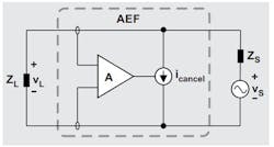
Active EMI filters (AEF) are a perfect alternative to bulky and expensive passive filters. An integrated AEF can be designed with active circuits to sense noise and inject a proper cancellation signal (icancel) that will reduce EMI (Fig. 1).
In Figure 1, vS is a noise source, ZS is the internal impedance, vL amplifies the noise voltage, icancel is the cancellation current, and ZL is the load.
Soft-Switching Reduces EMI Generation
Inverters that employ soft-switching are collectively called resonant inverters. In this class of inverters, the power switch will change switching states from turning on to off and then turning off to back on. Then the power switch will have no voltage across it with no current flowing through it. This action classifies the soft-switched inverter.
Such inverters reduce EMI, switching stress, and switching power losses.
Shielding
Shielding is the primary method that will enable electromagnetic (EM) protection and compatibility. Shielding uses materials to protect sensitive devices from disruption; however, EM shields will negatively affect the weight, volume, and the performance of a vehicle. The shield design must minimize the enclosure discontinuities and seal them to ensure a uniform, conductive surface.
Advanced shielding also is necessary to protect the cable from the environmental EMI effects as well as prevent it from releasing EMI to the environment.
EMC in the Electronic Drive Unit
Electromagnetic compatibility (EMC) is “the ability of electrical and electronic systems, equipment, and devices to operate in an intended electromagnetic environment within a defined safety margin, without suffering or causing unacceptable degradation as a result of electromagnetic interference.” (ANSI C64.14-1992).
An EV’s electronic drive unit (EDU) is actually the powertrain in the vehicle. The EDU is composed of the electric motor, transmission, and power electronics module (PEM).
EMC problems are one of the top design issues in an EV at the outset of a design.
Electric Motor
A motor design engineer will need to focus on certain EMC aspects to keep noise interference at a minimum in addition to optimizing control accuracy. Such design aspects include:
- Busbar: This device is a much better option than cables in the EV thanks to their high current density. Regarding EMC, the busbar helps to shorten the length of cables that run between the motor’s terminals and the high-power switches. EV busbars are typically designed to have the smallest loop area, especially when “interleaving” laminated busbars. Parasitic series inductances, along with parasitic shunt capacitance, will lead to a greatly improved EMC design.
- End winding: An optimum electric-motor winding arrangement will determine the magnetomotive force (MMF) as well as the shape of the amplitude and waveform generated voltages.
- Turn-to-turn: Motor windings should not be seen only as simple inductors. To truly understand any EMC issues, each winding configuration within the stator has a parasitic capacitance that’s caused by turn-to-turn proximity, known as interwinding capacitance.
Traction Systems
Electric vehicles typically have power electronic traction systems in the 100-kW range and battery voltages of up to 800 V. These traction-drive systems usually will produce a great deal of broadband EMI and can affect the vehicle’s EMC.
To provide a safe and stable parallel operation of the vehicle’s 12-V wiring system and the high-voltage (HV) traction system, the HV system is designed into the overall vehicle system. However, it’s completely isolated from the 12-V system (IT network), featuring a great deal of shielding.
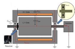
The shaft of the motor is directly connected to the 12-V ground, but it’s not integrated into the shielding, so it will be a weak point in this system. Broadband emissions, generated by the drive inverter, will flow through the shaft into the gearbox and on into areas like the wheel sensors and other parts of the 12-V system.
The resolver, another component directly connected to the 12-V side of the inverter, is located directly at the shaft. In this case, the high-frequency components of the motor current are able to directly couple into the inverter’s 12-V side via the resolver cable (Fig. 2).
Summary
A key automotive design objective is to have excellent signal integrity. Thus, any circuit should be able to adequately reject EMI and exhibit good EMC. Achieving EMC necessitates an intense study of the entire product design structure, which typically ranges from PCBs and power supplies to cables and enclosures. A strong design will ensure compatibility between digital and analog circuits, with a carefully designed layout and using solid shielding practices.
Designers must reduce radiated emissions while focusing on methods to increase radiated immunity via lowest-impedance return paths coupled with a continuous ground plan. Finally, designers need to add adequate protection circuits for input, output, and power signals.
Read more articles in the TechXchange: Delving into EMI, EMC and Noise
References
1. “Active EMI filters to reduce size and cost of EMI filters in automotive systems,” Texas Instruments
2. “EMI and Safety: Hazards, Risks, and Designing to Avoid Them,” Cadence PCB Solutions
3. “Demystifying EMC in an Electric Vehicle’s Drive Unit”
4. “EMC in Electric Vehicle Traction Systems,” VDI conference


