One test is worth a thousand expert opinions.
A large aerospace company designed a structure that was to be dropped from several miles up in the at-mosphere and free fall to the ground. The company's engineers had theorized what the 6-degree-of-freedom (6 DOF) motion characteristics of the structure during free fall would be as well as the orientation of the structure at ground impact. They had witnessed the stable behavior of similar test articles in previous drop tests but wanted to push the envelope this time by showing the structure would recover from a tumbling condition.
To further test the theory, they wanted to perform drop tests of the structure, instrumented with a unique 6 DOF measurement package. The package was intended to capture rotational motion characteristics during the drop and decelerations at ground impact.
When searching for a vendor to provide a self-contained sensing and recording package, the aerospace firm contacted Instrumented Sensor Technology (IST) in late 2004. The measurement objectives were to capture three-axis acceleration data over a range from 0 to 1,000 gs at earth impact only as well as continuous angular rate measurements (roll, pitch, and yaw) over a range of 0• to 300 /s in three axes simultaneously.
The measurement package needed to be very robust and compact to fit inside the small test structure as well as survive the ground-impact acceleration levels predicted to be in the range of 500 to 1,000 gs. The ground impact velocity was estimated to be around 70 mph.
After reviewing the test requirements, IST proposed using its EDR-4M6 Series Data Recorder supplied with a specially designed 6 DOF sensor package exterior to the recorder. The self-powered, programmable, digital recording package offers six high-speed recording channels that can be preset to digitize from 15 to 50,000 S/s/channel and in event blocks up to 16 kS in length.
The base unit is supplied with 12 MB of onboard storage expandable to 48 MB. The channels can be configured to trigger on threshold level crossing, time intervals, or by external trigger. The unit also features pre-trigger capability to assure capture of the leading edge of events prior to exceeding the trigger level.
Recorder Setup
For the drop tests, the data recorder was programmed with the following parameters:
Accelerometer Channels
• Digitization Rate: 6,000 S/s/ch
• Post-trigger: 8,192 samples
• Trigger Level: 50 gs all three channels
Angular Rate Channels
• Digitization Rate: 1,024 S/s/ch
• Pre-Trigger: 120 event blocks
• Post-Trigger: 10,000 event blocks
• Trigger Level: 0 /s all three channels
The accelerometer channels were configured to capture only the ground impact acceleration profiles while the angular rate sensor channels were set up to capture continuous rate data during the structure's free fall. Once the recorder was activated, it took continuous 3-axis rate data while waiting for a 50-gs trigger to capture the ground impact data.
The digitization rate and memory allocation for the rate sensors allowed several minutes of pre-drop test activity, minutes of free fall, and additional time sitting on the ground post-impact while in the continuous record mode. Recovery of the system and download of the data took about 20 minutes and ascent in the helicopter about 20 minutes, allowing for approximately one test per hour.
The Drop Tests
The drop tests were conducted earlier this year in Utah. Several sets of structures were prepared for the drops because the customer wanted to gather as much data as possible. A helicopter elevated the structure to an altitude of approximately 10,000 ft above ground level. The air temperature at altitude was reported to be between -30• and -50 F.
The customer had several concerns regarding the drop tests:
• Would the data recorder survive the ground impact?
• Would the angular rate sensors survive the high g ground impact?
• Would the recorder survive the cold temperatures at altitude?
• Would the rotor wash generated by the helicopter induce such high-momentum angular rates that the retarding aero forces could not stabilize the structure?
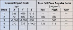
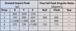
Five drop tests were successfully completed before a catastrophic instrumentation failure occurred. Data was collected on all five drops; however, during the fifth drop at ground impact, the accelerometer channel connector on the recorder housing was sheered off. This was a result of the high-impact acceleration levels and direct impact of the connector as evidenced by the reversed acceleration direction for this test. Results from the five drop tests are listed in Table 1.
On the first drop, the structure fell on a bush and the resulting g levels were lower than on subsequent drops. No rate data was captured on the first drop as a result of an undiagnosed failure on the rate sensor data acquisition electronics. However, the recorder has a tested fragility specification of 500 gs, and this was exceeded on the first drop.
Interestingly, one of the data recorder's four internal D-cell batteries was hot to the touch immediately after the drop test, indicating a possible internal battery short possibly resulting from the high-g impact levels. All the batteries were replaced between subsequent drop tests. The impact orientation also was off-nominal.
On the second drop, a hard ground impact, the recording package captured data on all six channels. The roll data channel appeared to be saturated during the free fall but, in actuality, represented the high spin rate induced by the test engineer in an effort to eliminate the initial tumbling effects caused by the rotor wash. Again, the structure did not impact the ground on the Z-axis but more along the X-axis.
Additionally, large amounts of yaw and pitch were measured during the descent, more than was predicted. The angular rate time-history plots during the free fall are shown in Figure 1. After this drop, another D-cell battery was observed to be hot to the touch; however, it was a different battery than the one on the first drop.
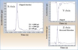
On the third drop, a hard ground impact, the orientation again was not along the Z-axis but more along X and Y, and the g levels clipped out at more than 1,000 gs. The impact acceleration profiles for this drop are shown in Figure 2.
A computation of the resultant delta-V (change in velocity) from the acceleration profiles for this impact comes in at 64.7 mph, quite close to the predicted 70 mph. However, since the accelerometer signals were clipped at 1,000 gs, the actual delta-V was higher.
The pitch and yaw channels clipped during this drop due to excessive tumbling caused by the 100-mph shear effects of the helicopter rotor wash. The roll channel shows what appears to be an electronic DC offset but, in reality, is a measure of an attempt to stabilize the structure by imparting a Frisbee spin.
On the fourth drop, another hard ground impact, the impact orientation primarily was along the Z-axis and again clipped in excess of 1,000 gs. Measurements on the pitch and yaw finally showed a stabilized structure as verified by the tracking video and contained significant aero-damping effects as hoped (Figure 3). Indeed, one test is worth a thousand expert opinions.
On the fifth drop, the accelerometer data was lost as a result of a connector failure. The g levels were likely the highest on this drop and caused the shearing of the connector and cabling from the sidewall of the recorder and signal loss during the ground impact. This affected the rate sensor data as well, and the data appeared compromised.
Conclusions
The instrumentation package was very useful in providing numeric validation of what was witnessed on video for the free fall and the measurement data that was needed to characterize impact. As a result of the extremely high-impact g levels, some of the measurements were compromised or lost. However, there was sufficient data to indicate that the structure did posses the characteristics to stabilize and that the initial conditions created by a helicopter drop are quite severe.
Subsequent to this drop test sequence, the recording package was returned to the IST factory for repair. The sidewall connector assembly was replaced with a solid through-wall cable with strain relief, eliminating the connectors for improved reliability. No other internal damage was discovered within the unit.
About the Author
Greg Hoshal, who founded the company in 1987, is president and CEO of Instrumented Sensor Technology. Mr. Hoshal graduated from Michigan State University with B.S. and M.S.E.E. degrees and has published numerous papers and spoken at a number of technical symposiums around the world. He holds two U.S. patents related to sensors and data recording technology and has one patent pending. Instrumented Sensor Technology, 4704 Moore St., Okemos, MI 48864, 517-349-8487, e-mail: [email protected]
FOR MORE INFORMATION
on the EDR-4M6 Data Recorder
www.rsleads.com/506ee-221


