Software-defined radio (SDR) is a very powerful concept. Its technologies provide software implementation of modulation, interference management, and capacity enhancement techniques over a broad frequency spectrum while ensuring secure communications management.
There remains a key issue that has yet to be resolved: how to verify the performance of an SDR. This verification is important because radios have many limitations independent of the software running on them. For example, the software may be able to tell the radio to tune to a particular frequency and set the output power level, but if the radio's amplifiers, matching networks, and antennas don't have those capabilities, the radio isn't going to work. This dichotomy creates a critical need for a way to verify the underlying analog capabilities of an SDR.
Presently, there is no single-instrument SDR transmitter tester or radio conformance tester. Testing an SDR platform requires both a test signal source and a wideband signal analyzer, so engineers are creating their own solutions that combine a signal analyzer, an Arb-based vector signal generator, and analysis software. Both instruments, when used in SDR testing, must provide a frequency from 0.5 MHz to 3 GHz to cover the radio's range while also having enough instantaneous bandwidth to handle different SDR modulation formats.
Engineers also need to establish SDR verification philosophies based on certain criteria that include both hardware and software tests. When establishing the verification philosophies, engineers must consider some important RF measurements including power, frequency response, phase noise, and spurious signals. Modulation quality measurements, such as error vector magnitude (EVM), can be done on a variety of signals to verify the baseband and IF signal processing capabilities of the radio.
Power
Average power is a traditional measurement that carries over to SDR applications. However, there are new considerations that make power measurements more difficult. Digital radios can have very high peaks. For example, multicarrier WCDMA or OFDM signals can have peak power of >10 dB. Utilizing peak-reduction technology is helpful but it may adversely affect the error rate.
The advanced amplifier technologies used in SDR development also must be considered when making power measurements. Some communications standards define test signals with known peaks, such as WCDMA Test Model 1, while other communications standards have not developed such test signals.
Even measurements as simple as signal power depend on considerations such as whether the signal is bursted and what signal is used for a trigger event. Other factors include the signal's bandwidth and whether external components are between the test equipment and the DUT. Many modern signal analyzers and power meters can make these measurements, but engineers must be aware that measuring a particular kind of signal may be beyond the capabilities of a specific instrument.
For example, measuring bursted signals with an average power meter is problematic. It may not allow a particular part of a signal to be measured such as a preamble or other training sequence that is sometimes used as a power reference.
A peak power meter or signal analyzer is a better choice for measuring the power on bursted signals. Some signals even require synchronization to a particular part of the demodulated signal, which makes a signal analyzer the instrument of choice.
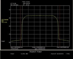
An example of a simple power measurement using a signal analyzer is shown in Figure 1. In this case, the signal is not bursted so a simple swept spectrum of the signal with averaging can be viewed. Then the power can be determined by integrating across the frequency band of interest. This is the channel power measurement shown below the spectrum.
Figure 1. Measurement of an SDR's Power Using a Signal Analyzer
Please click here to see larger image
Frequency Response
In SDR applications, receiver equalization compensates for frequency response. However, frequency response variations can have an impact on the effective coverage area of a network because these variations reduce the margin at the receiver.
For example, a 1-dB frequency response variation might cause as much as a 1-dB, or about 20%, change in coverage area. This is a very important factor. The coverage area is critical for commercial networks because it affects the number of expensive base stations that must be deployed.
SDRs also may use spread-spectrum operation. The result is of greater importance in the RF frequency response requirement due to the wider range of RF frequencies that may be used.
This frequency response can be measured in a variety of ways. If you are measuring the components used in the radio, a vector network analyzer (VNA) often is the instrument of choice because it provides extremely accurate measurements. If the entire radio needs to be measured, a signal analyzer or power meter is the correct instrument to use. When you are measuring components or subsystems and need additional measurements such as modulation quality on the same DUT, a signal analyzer and vector signal generator can be a good combination for the frequency response measurements.
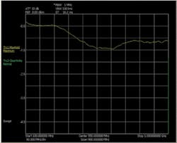
Depending on the particular conditions, you might measure the level of CW or modulated signals at various frequencies, measure a modulated signal and use a measurement equalizer, or use specialized test signals such as chirps, noise, or noise-like signals. Figure 2 shows an example of measuring the CW signal from a signal generator through a fairly flat amplifier over the frequency range of 100 MHz to 1 GHz.
Figure 2. CW Signal Level Measured Through an Amplifier Over a 100-MHz to 1-GHz Range
Please click here to see larger image
In this case, the signal generator was stepped in 1-MHz increments, and the signal analyzer was set to the Max Hold trace function to capture the entire frequency range. There is approximately 1-dB variation peak-to-peak across the frequency range.
Phase Noise
To determine phase noise requirements in an SDR, engineers must consider both the transmitter and receiver local oscillator requirements along with the receiver's timing recovery. This is difficult considering that timing recovery usually is unspecified.
Phase noise is a common measurement for oscillators, and modern signal analyzers often have optional capability for making these measurements and showing the results in graphical form. The offset range, sweep type (FFT or swept), and amount of averaging usually are adjustable depending on the testing parameters.
By overlaying multiple measurements, comparisons can be made of device performance under various conditions, such as carrier frequency, bias voltage, or temperature. This creates a much more accurate determination of an SDR hardware performance.
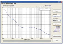
An example phase noise measurement of a 2-GHz synthesized oscillator with a jitter measurement of 102 fs between 100 Hz and 100 kHz offset can be seen in Figure 3.
Figure 3. Phase Noise and Jitter Measurements of a 2-GHz Synthesized Oscillator
Spurious Signals
Measuring the harmonics, intermodulation, and other spurious signals of an SDR is extremely complex. Typically, third- or fifth-order harmonics must be measured, but in some designs, even higher order harmonics need to be determined.
Harmonics and intermodulation usually are dominated by the power amplifier and vary depending on the power level and amplitude statistics. Spurious signals can come from a variety of places including oscillator leakage and intermodulation products.
Intermodulation can cause many unwanted responses including adjacent and alternate channel interference. Multiple transmitters situated near each other also can intermodulate, causing interference signals to appear at a wide variety of possible frequencies.
Measuring harmonics and intermodulation is best done using a signal analyzer or spectrum analyzer so the level of the intermodulation signal in the presence of the transmitted signals can be seen.
The dynamic range of the signal analyzer is critical to these measurements. For some signal types, however, the measurement requirements exceed the capabilities of even the best signal analyzers. In these cases, special techniques are required, such as measuring the signal before a transmitter's output filter or using filters to eliminate the large transmitted signal from the input of the signal analyzer.
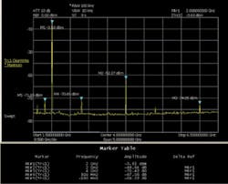
Figure 4 is a sweep showing harmonics and spurious signals on the same 2-GHz synthesized oscillator. The relative and absolute level of the harmonics and major spurious signals are shown. For example, the second harmonic is at -52 dBm or about 49 dB below the carrier.
Figure 4. Harmonics and Spurious Signals on a 2-GHz Synthesized Oscillator
Please click here to see larger image
Linearity
The performance of RF components varies with power level as well as amplitude statistics. Traditional FM waveforms, for example, are very easy for amplifiers because the amplitude is constant.
However, many types of digital modulation can have a very large variation in amplitude. These variations place large demands on the analog components, especially the transmitter's power amplifier. Two key measurements that can help are linearity, also known as power sweep or gain compression, which is usually measured with a VNA, and the complementary cumulative distribution function (CCDF) measured with a signal analyzer or peak power meter.
The CCDF measurement shows the probability of a peak occurring in a signal and is useful for two reasons:● The size of a signal's peaks can be seen, allowing for a comparison of the peak size to the linearity measurements made on a VNA. This will indicate if the signal will be compressed and, if so, by how much. ● A comparison of the CCDF can be done to determine if any compression is happening. If there is compression, it also will indicate how much and how often. Modulation Quality
The best measure of a radio's capability to send high-quality signals is to directly measure the modulation quality. A variety of measurements can all indicate the relative level of the signal to everything else noise, phase noise, jitter, distortion, and in some cases, frequency response errors. Unfortunately, EVM is somewhat specific to the particular modulation parameters currently being used.
Just because EVM is low for one symbol rate, for example, it is not necessarily also low for another symbol rate. As a result, EVM is an excellent check of the radio's analog performance for a particular set of conditions but not necessarily indicative of another set of conditions.
In addition to EVM and the related overall metrics of Rho, relative constellation error (RCE), and modulation error ratio (MER), there are a number of other measurements that can be used for troubleshooting tools. For example, measurements of I/Q imbalance, carrier leakage, and quadrature error indicate the gain match, offset, and phase match of analog modulators. EVM vs. time can show amplitude droop or frequency drift. EVM vs. frequency can help find IF frequency response errors and interfering spurious signals.
When measuring modulation quality of a complete transmitter, the signal analyzer is the correct tool to use. A set of measurement functions that verifies the performance of an SDR's transmitter, such as channel power, adjacent-channel power ratio (ACPR), occupied bandwidth (OBW), and modulation quality measurements for the QAM and PSK signals often found in SDRs, can be conducted with this type of instrument.
If you have components or subsystems to measure, a signal analyzer and a vector signal generator are ideal for modulation quality measurements. In this case, the combination signal analyzer/vector signal generator allows real-world testing scenarios to be created.
The vector signal generator can act like the software-programmable transmitter portion of an SDR, allowing the generator to be programmed for existing and emerging waveforms. If the generator has a dual memory design, you also can use it to emulate a pair of waveforms to add controlled noise or interference to the test signal, allowing measurements under real-world conditions.
Conclusion
Test tools for SDR RF measurements should effectively emulate the behavior of the radio's receiver and transmitter sections with adequate frequency range, wide modulation and demodulation bandwidths, wide dynamic range, and excellent level accuracy to handle existing and emerging SDR designs. These tools must include flexible test instruments that allow standard modulation and custom modulation analysis to be performed.
About the Author
Eric Hakanson is a product marketing manager in the Microwave Measurements Division of Anritsu Company, an SDR Forum member. He has worked in the test and measurement industry for more than 25 years in various marketing roles. Mr. Hakanson received a B.S.E.E. from Virginia Tech. Anritsu Company, Microwave Measurements Division, 490 Jarvis Dr., Morgan Hill, CA 95037-2809, 800-267-4878, e-mail: [email protected]
FOR MORE INFORMATION
on the SDR Forum
www.rsleads.com/704ee-177

