Hipot data? That is an oxymoron. A hipot test, also known as dielectric breakdown, is a simple test: Apply high voltage to the insulation barrier of the DUT and ensure there is no breakdown. It is a simple pass/fail test—no need for data.
Then why are more and more manufacturers requesting the capability to collect data from hipot test? Quite simply, safety standard requirements.
What the Standards Say
Most standards state similar requirements for the dielectric withstand test. They specify a voltage and test time and require that no breakdown occur while the voltage is being applied.
• 61010-1 Electrical Equipment for Measurement, Control, and Laboratory Use
6.8.4 No breakdown or repeated flashover shall occur. Corona effects and/or similar phenomena are disregarded.
• 60601-1 Medical
8.8.3 During the test, breakdown is considered a failure. Insulation breakdown is considered to have occurred when the current which flows as a result of the application of the test voltage rapidly increases in an uncontrolled manner; that is, the insulation does not restrict the flow of current. Corona discharge or a single momentary flashover is not regarded as insulation breakdown.
• UL 507 Electric Fans
34.1 a) One thousand volts for an appliance employing a motor rated 372.85 watts (1/2 horsepower) or less and rated 250 volts or less.
34.2.1 The test equipment for conducting the dielectric voltage-withstand test is to be adjusted for sensitivity such that when a resistor of 120,000 ohms is connected across the output, the test equipment does not indicate unacceptable performance for any output voltage less than the specified test voltage, and the test equipment does indicate unacceptable performance for any output voltage equal to or greater than the specified test value. The resistance of the calibrating resistor is to be adjusted as close to 120,000 ohms as instrument accuracy can provide, and not more than 120,000 ohms.
Looking at the 120-k? rule of thumb, when testing is performed at 1,000 V and the tester is adjusted so that breakdown occurs if the resistance of the product is less than 120 k? then the maximum allowable leakage current would be 8.333 mA (1,000 V/120,000 ? = 8.333 mA).
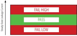
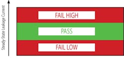
New standards do not use a fixed value resistor; they simply state that breakdown shall not occur. Today, dielectric withstand testers provide quite a bit of flexibility for programming the limits to determine pass/fail. So what should the high limit be set to? As shown in Figure 1, when the leakage current of the DUT exceeds the high limit, it is considered to be a failure.
Figure 1. Pass/High-Low Fail as a Function of Leakage Current
High Limit
Some standards state minimum insulation resistance requirements for the product. For example, Class I appliances typically have a minimum insulation requirement of 2 M? If the dielectric withstand test is performed at 1,500 V, the expected leakage based on the minimum insulation requirement would be 0.75 mA.
You may consider setting a limit slightly higher than the calculated value, such as 0.80 mA. Practically speaking, however, this may not work.
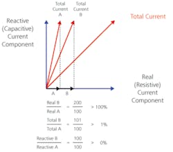
Leakage from an AC test is made up of resistive and reactive current. If the product has any capacitance within it, reactive current will be present in addition to the resistive current, resulting in a leakage current not correlating to the calculated value from the insulation. In products where there are large amounts of capacitance, the reactive current could mask the real current, making it impossible to measure the actual leakage through insulation.
Figure 2 shows both total and real leakage current components. The real limit would be set based on the calculation using the insulation requirement. The limit that corresponds to the high limit then can be set higher to accommodate the additional reactive current. If the capacitance of the product is negligible, once the capacitors have been charged, using a DC voltage can provide a leakage which corresponds directly to the insulation.
Figure 2. Chart of Leakage Current Components
Line Leakage Current
Line leakage current flows from the mains of the DUT through or across the insulation into earth. It is measured with the DUT operating at its nominal line voltage; in some cases, 10% greater than line voltage. This current is a good representation of the insulation and impedance of the product. Using the impedance calculation obtained from the line voltage and leakage current, you can calculate an approximate dielectric withstand current:
For example, for a product with a nominal line voltage of 240 V, an acceptable line leakage current for a grounded product may be 3 mA. Applying Ohm’s law we can determine the product impedance to be 80 k? If the voltage requirement is 1,500 V and we know the impedance is 80 k? we can expect a leakage of 18.75 mA.
Even when the earth leakage current of the product is unknown, the safety standard has actual limits based on the class of the DUT. For instance, a Class I hand-held product requires the leakage current to be less than 0.75 mA. To meet this requirement, if the product is being powered by 240 V, the impedance of this product must be at least 320 k? If tested at 1,500 V, the current would be 4.6875 mA, and a high limit of 5 mA may be reasonable.
Using Data to Set the High Limit
Setting the high limit based on insulation or leakage current requirements may be a valid method. Statistically using known data is a very good way to determine the high limit, the safety of the DUT, and consistency of the manufacturing process.
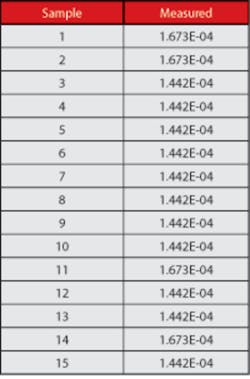
Using a variable sampling plan, known-good product is selected from each lot. The leakage is measured, and the normal distribution among the samples is determined. Table 1 shows the measurements of 15 samples.
The average of these measurements is 1.5038E-4; the standard deviation of the measurements is 1.058E-5. Taking a Six Sigma approach, we can calculate with 95% confidence that all good product will fall within this limit:
High Limit = 3S +X
Applying this formula:
Adding some headroom, a recommended high limit may be 0.2000 mA for this example. This will ensure the product is safe and the process in producing the product is consistent.
Low Limits
There is nothing worse than believing the correct voltage is being applied to a DUT only to find out a cable is broken and the only thing that has been tested is the hipot tester itself and part of the cable. This is especially true if this fault was not caught in time and product has already been shipped to the customer. While a skilled operator may notice a difference in leakage, collecting and evaluating the data on a regular basis may reduce such an error.
Setting the proper low limit will ensure the hipot test fails if the DUT is not connected or the power switch is turned off during test, another common mistake among operators performing hipot. The low limit can be determined statistically using the method discussed to determine the high limit:
The results shown in Table 1 fall within both the high limit and the low limit, resulting in a pass test. If the measurement is greater than the high limit, the test will be considered a fail. Although breakdown may not have occurred within the product, something has changed, and the engineers should be alerted.
Part Variation
As a result of setting limits for the hipot test, a medical device manufacturer was able to determine components within a product had changed. The product contained two redundant patient connections: If one circuit fails, there is a back-up circuit in place. A standard test for medical products is mains voltage to patient connection hipot. This ensures the patient connection is fully isolated from mains voltage.
The two patient circuits produce similar hipot test leakage readings. Over time, it was observed that one of the two mains to patient hipot test leakage current readings was higher than the other. There was no evidence of breakdown; however, the leakage readings were approaching the limits set forth for the high limit.
Through investigation it was found one of the op-amps in the circuit had been replaced with a comparable part. This replacement went through the proper validation and testing; however, the testing on the manufacturing floor had tighter limits than the compliance tests looking for no breakdown to occur. Without data, this change would have gone unnoticed until the product began producing a failure.
Process Variation
A component manufacturer had one batch of product pass, one batch fail. Investigation showed both parts were manufactured identically using the same materials and same process. Reviewing test data was the only hope to determine the difference in batches.
Examination of the data showed the only difference between the two batches was the time in which the test occurred. The last step in the process before test is a final bake. One batch was tested immediately after the bake; the second batch was tested after lunch. The batch that sat after bake acquired moisture within the coating, resulting in the hipot test failure. The batch that was tested immediately after the bake process passed because the parts had not sat long enough to build up moisture. Without data, which provided the time of test, the manufacturing engineers would have spent days determining why the two batches resulted in such drastically different results.
He Said, She Said
Manufacturer ships product. Customer receives product. The product is faulty. Manufacturer says the product was good when it shipped.
More and more manufacturers are combining hipot test with functional tests. For example, an industrial supply manufacturer is performing functional tests with hipot, recording both the hipot test results as well as resistance readings for the heaters and current draw measurements of the product. Previously, simple pass/fail test results were checked on the product traveler.
The product would ship and be installed in the field. Then support engineers of the manufacturer would get a call that the product was defective. Prior to collecting data, the support engineers had no data to prove the product was properly tested before shipment. The product would be returned to the manufacturer where nothing was found to be wrong.
This became an ongoing occurrence with one particular customer. The manufacturer implemented a solution which automated the testing process and collected data along the way. The support engineers were able to pull up data based on the serial number of the product and send it to their customer to show the product was tested and functioning properly at the time of shipment. At this point, they could begin troubleshooting why the product was not working. Prior to having data, the customer would not take the time to troubleshoot. The company simply wanted a replacement because the product received was defective.
Traceability
The once-simple pass/fail hipot test is converging to a who, what, when, and how the part was tested—particularly for the medical, military, and aerospace industries. Many other industries are following suit.
In addition to performance issues, manufacturers are requiring the leakage readings for other reasons. The test data also is being used to determine who is performing the test, tracing results back to the operators. Operator data has been used to determine variation in results from operator to operator and productivity of each operator while providing accountability.
Traceability back to the equipment used to perform the test is extremely helpful when the test equipment is calibrated and found to be out of specification. Knowing where the equipment is out of specification, how far the reading may be off, and what the measured results were with that equipment can easily prevent a recall from occurring.
Operators like to push buttons. If there is a knob to turn, it is likely to get moved. This innocent adjustment could change the voltage at which a product is being tested. Data that shows the leakage reading as well as the voltage applied to the DUT provides a traceable record that the device not only was tested, but tested with the correct voltage.
Hipot is a simple test: The product shall show no sign of breakdown. It is the data behind the hipot test that can help manufacturers ensure the product is safe and consistent. The proof is in the data.
About the Author
Shari Richardson is a director of engineering and the lead engineer on all medical applications at QuadTech. Prior to joining QuadTech in 2001 as an applications engineer, she was a senior process engineer at Biz2Net Technologies and earned a B.S.E.E. from the University of Massachusetts. Ms. Richardson has written many articles and been a guest speaker and presenter at the Product Safety Engineering Society Symposium.
e-mail: [email protected]
Published June, 2010


