The field strength used to determine radiated immunity must be accurately monitored during any test although the levels vary greatly from consumer to military applications. At high frequencies, this is the job of electric (E) field probes; at low frequencies, magnetic effects dominate.
E and magnetic (H) fields accompany all current flow, and most of the time, they cause few disruptions. However, avoiding or eliminating unwanted interactions is what EMC testing is all about, and it takes several forms. To get a better understanding of EMC issues at the design stage, an engineer may explore local E and H fields using small probes.
These probes are easily made by connecting a simple loop of wire between the center conductor and shield of a coax cable. This probe will indeed pick up signals when placed close to a conductor, but it is sensitive to both E and H fields. With a bit more work, you can suppress one or the other type of field and get a better idea of how your circuit is behaving.
A number of manufacturers sell passive probes, sometimes called sniffer probes, for troubleshooting. Com-Power’s PS-400 and PS-500 Near Field Probe Sets are good examples having three and four probes, respectively, in a wooden case. The idea is to use the tool to find the source of a problem so that it can be corrected. By comparing the before and after measurements, you can see the degree of improvement.
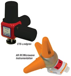
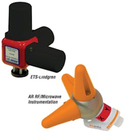
Figure 1. Typical Three-Sensor Integrated Isotropic E-Field Probes
E-Field Probes
Another class of probes has been specifically developed for monitoring EMC immunity test fields. These probes consist of special sensors with associated signal-processing electronics and are designed to have minimal impact on their surroundings. A popular integrated form, shown in Figure 1, has orthogonal sensors and can measure field strength in all three directions as well as the vector sum. Typically, the probes are used with a control chassis that further processes and displays output values and may provide electrical power.
The sensitivity of an E-field sensor usually is very low precisely because it has been designed to have minimal effect on the field being measured. Accordingly, the signal conditioning and amplification within a probe using E-field sensors are designed to handle small signals. The most important characteristics of such a probe are linearity and isotropy.
Linearity primarily varies with field strength and much less with frequency while isotropy depends largely on symmetry. Both characteristics are related to the probe’s construction, stalk-mounted probes being better suited to very high-frequency work than integrated probes.
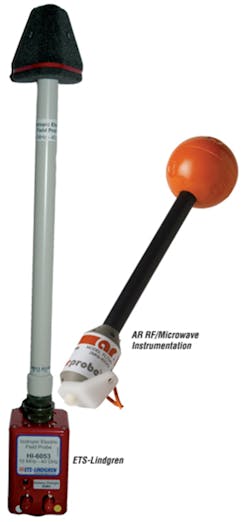
Isotropy errors occur partially because the probe body and internal electronics are sensitive to their orientation within the field. The probe body also may distort the field as measured by the sensor. Stalk-mounted probes, as shown in Figure 2, minimize the volume that intrudes into the field being measured and house at least some of the associated electronics away from that area. The advantage a stalk-mounted probe may have can be reduced by incorrectly choosing the mounting angle relative to the field.
Figure 2. Typical Stalk-Mounted Isotropic
E-Field Probes
To further minimize field disturbance and unintentional probe coupling, fiber-optic cables rather than metallic conductors are used to communicate with this type of probe. Some probe models are battery powered, an example being the AR RF/Microwave Instrumentation Model FP7003 with rechargeable NiMH batteries having a 40-hour operating life per charge. Other models, such as the company’s FL7040, use a second fiber-optic cable to couple laser light that is converted to electricity within the probe. This type is intended for long-term monitoring in fixed test setups. Battery-powered probes are better suited to ad hoc on-site measurements.
AR’s Jason Smith, manager of applications engineering at the RF/Microwave Instrumentation Division, explained, “The FL7xxx Series probes cover the 5-kHz to 60-GHz range. Automatic temperature compensation is possible because each antenna element on every probe is characterized over its specified temperature and amplitude range. These probes use technology to reduce the size of the electronics while housing them in a sphere. The result is a minimal disturbance of the E-field, which reduces measurement errors.”
As with any precision measurements, details make the difference. Rather than having only one composite correction factor, it’s much better to have one for each axis. This means that individual sensor variations can be accommodated. In addition, the type of sensor is important. A dual-diode sensor provides full-wave detection that measures both the positive and negative portions of the waveform. Some types of amplifiers used to establish test fields may distort the signal on only one polarity, leading to measurement errors if a single diode-based probe were used.
Calibrate for the Application
According to an ETS-Lindgren paper delivered at a 2009 EMC Symposium workshop session, “Modern probes have [the] correction table built into the probe. Microcontrollers inside the probes apply linearity correction. Since probe linearity response is a weak function of frequency, comprehensive calibration in linearity responses at different frequencies can be collected but is typically not necessary (there will be [an] overwhelming amount of data). Frequency response correction is applied during end use.”1
D.A.R.E!! Development added some clarification. The frequency response is the frequency-dependent deviation or error over the complete operating range. During calibration of an E-field probe, these frequency-dependent deviations are registered and stored in a correction factor table. The table for every probe orientation should be entered in the measurement software to ensure valid readings with deviations no larger than the measurement uncertainty.2
In general, there is a benefit to calibrating a probe with signals similar to those it will measure in the actual application. Probes are calibrated and intended for use in a CW field. Data presented in Reference 1 shows sensitivity to the wave shape, the response to a square wave being higher than for a sine and that for a sine higher than for a sawtooth waveform.
For modulated fields required in some tests, “The correction factor of a probe can depend strongly on the field strength and the modulation depth. Particular attention should be paid to pulsed fields.”2
In fact, AR’s Model PL7004 E-field Probe is designed specifically for use in measuring pulsed E fields. Among other requirements, the probe was developed to address automotive radar pulse tests such as General Motors’ GMW3097 and Ford’s ES-XW7T-1A278-AC. According to the datasheet, response-smoothing time constants are used to provide consistent readings for pulse rates as low as 200 Hz.
Innovative Isotropy
Patrick Dijkstra, director of D.A.R.E!! Instruments, said that the company introduced the first laser-powered RadiSense® Probe in 1999. Development has continued since then, resulting in a series of small probes dealing with field strength from 0.2 V/m to 4,000V/m. At the IBM Munich Test Center, similar D.A.R.E!! probes are used from 9 kHz to 4 GHz for field strengths up to 200 V/m.
Mr. Dijkstra explained that many E-field probe datasheets relate to “rotational symmetry, which is quite different from being isotropic. In most cases, [calibration is performed] by rotating the probes with the three axes symmetrical in the field.” In actual use, this can lead to large measurement errors because the field direction relative to the probe elements may not be known.
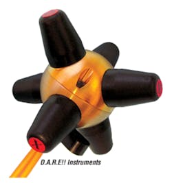
To alleviate this problem, D.A.R.E!! has developed the RadiSense-8 Field Probe with a 10-MHz to 8-GHz frequency range and 1-dB total anisotropy. As Figure 3 shows, the probe has six elements. “The improved isotropic values over a larger frequency range are reached by short elements compared to the size of the sphere and the use of six axes,” commented Mr. Dijkstra.
Figure 3. RadiSense-8 E-Field Probe
With Six Sensors
H-Field Testing
Magnetic radiated immunity testing is broken into frequency bands because of the different apparatus required. At low frequencies, large Helmholtz coils driven by power amplifiers are used to establish a uniform field. A monitoring probe can be as simple as a small coil of wire. The coil is inserted between the Helmholtz coils in the same position where the DUT will be placed for test.
According to the user manual for the ETS-Lindgren Model 6400 Series Helmholtz Coils, “Precision in the manufacture of the [2 ft to 8 ft dia] coils and their support assembly is well within a design tolerance of 0.635 centimeter (0.250 inch) in both radius and axial separation. The limit of this tolerance would produce a maximum error of 0.55% in the accuracy of the magnetic field constant under the worst conditions. For this reason, the Helmholtz coil is considered a standard and produces a magnetic field whose accuracy is governed by the accuracy of the current monitoring equipment.”
Hall effect sensors cover a frequency range from DC to tens of kilohertz and commonly are used in low-frequency gaussmeters. F.W. Bell, a long-time supplier of these meters, has developed a GaAs-based Hall effect sensor that allows operation up to 50 kHz.
At higher frequencies, it becomes practical to use special forms of probes. ETS-Lindgren’s Model HI-4433-LFH and HI-4433-HCH Magnetic Field Probes have frequency ranges from 300 kHz to 30 MHz and 5 MHz to 300 MHz, respectively. Both offer isotropic detection with ±0.5-dB accuracy, linearity, and isotropic deviation. These are stalk-mounted 4″ diameter, 22″ long probes. The lower frequency LFH unit has a dynamic range from 300 mA/m to 30 A/m while the HCH range is from 30 mA/m to 3 A/m.
A paper presented at the 2009 EMC Symposium described an H-field probe with a frequency response greater than 1 GHz. Internally, the flex circuit-based sensor resembles an electrostatically shielded sniffer probe. A loop as small as 0.003″ x 0.003″ is shielded on all sides except for a 0.002″ gap.3
This type of sensor also is referred to as a B-Dot probe, meaning that it responds to the first derivative of the flux density (B field). In this particular case, no magnetic material is used that would distort the B-H relationship, and the permeability of the flex circuit substrate is taken as a constant. As a result, the voltage output from the sensor has a rising 6-dB/octave frequency response. The innovative part of the work is the use of an active oscilloscope probe as an integrator that, in combination with the sensor, provides an H-field probe with a flat frequency response.
The Agilent Model 1169A active probe gain follows a -6dB/octave characteristic from about 30 MHz to beyond 5 GHz. Typically, an active oscilloscope probe has a flat frequency response when used with its browser. But it was found that the amplifier part alone has a frequency domain response with a low frequency gain of 43.5 dB until 31.8 MHz and then a 20-dB/decade fall was observed. The frequency response of the active probe is like an integrator, which compensated for the first order derivative response of flex probe.3
Recovering the Data
Both ETS-Lindgren and AR have four-channel field monitor instruments, HI-6100 and FM7004, respectively. Each can be used for either E- or H-field probes, whether laser or battery powered. And, each instrument provides extensive display capabilities including the choice of separate elements within a probe.
However, the calibration factors that compensate for changes with frequency in a probe’s response are treated differently. For the FM7004, you can store up to six sets of correction factors in its internal memory. Each table of correction factors can contain up to 30 different frequency points. The tables are loaded on the FM7004 using the USB port and Table Loader program.
In contrast, there is no provision within the ETS-Lindgren HI-6100 Field Monitor to enter frequency calibration data. The unit displays maximum, minimum, and average readings from a selection of probes. Values for all three axes of each probe are presented as well as the composite field strength. Also, each probe’s temperature, operating voltage, and laser temperature and current are listed.
For a single channel, you can create a PC-based alternative solution by using the company’s HI-6113 Data Interface that connects to laser-powered probes and via the USB port to a PC. The HI-4413 fiber-optic modem is similar but communicates with the PC via RS-232. ProbeView™ Software provides data collection and display. In addition, data can be imported into MS-Excel for further manipulation. ProbeView features real-time display and logging of data from each individual axis as well as the resultant data.
Professional precompliance and compliance EMC test software accepts tables of calibration factors, and this is the meaning of the comment about applying frequency response correction during end use.1 ETS-Lindgren’s TILE!™, Teseq’s Compliance 5, AR’s SW1007, D.A.R.E!!’s RadiMation®, and Rohde & Schwarz’s EMC32 are examples of software applications used in EMC testing. In general, these programs support measurements to commercial standards such as CISPR, IEC, ISO, EN, ETSI, VDE, FCC, and ANSI.
Alternative Fields
Narda Safety Test Solutions claims to own more than 95% of all published patents for measuring E, H, and electromagnetic EM fields. Primarily, the company’s products monitor personal safety related to EM exposure or EMC of devices that use RF, such as induction heating and heat sealers.
The company’s NIM-511 and NIM-513 Industrial Field Meters simultaneously measure E and H fields from 10 MHz to 42 MHz and from 300 kHz to 100 MHz, respectively. For either model, the probe contains two sets of sensors to measure both the E and H fields. The instruments have isotropic response within ±1.0 dB and ±1.0-dB linearity.
Robert Johnson, director, instrument products at the company, described recent sensor innovation for a personal safety monitor: “We developed an ultra-wideband sensor for use in the new Nardalert S3 Monitor. This sensor occupies a 2″ x 2″ x 0.5″ volume and covers 20 kHz to 100 GHz, making it the smallest broadband antenna of its type in the world. This design employs thermocouple sensors that can accurately detect new modalities such as ultra-wideband signals.”
Further Considerations
There’s no shortage of available guidance on the use of E- and H-field probes. EMC test standards, application and technical notes from the probe manufacturers, and research papers all provide useful information. Nevertheless, a reasonable amount of caution must accompany the use of probes.
For example, stalk-mounted probes may have been calibrated with the connector box out of the measured field or at least covered with RF absorber material. Some probes have special critical-angle mounting hardware because orientation within the field is important.
Probe size makes a difference to the degree that a physically large probe will interact with a small test volume such as a Crawford TEM cell or GTEM cell. Of course, a sniffer probe that’s large compared to the circuit elements being examined can only integrate fields over a big area. The H-field probes described in Reference 3 were intended to measure the fields around individual IC leads, hence the very small loop size.
Even though an E-field probe’s output has only a weak dependence on frequency, you still need to account for frequency-related errors to achieve the most accurate results. Some datasheets include two graphs, one with a probe’s typical frequency-related deviation and the other showing the much narrower error band possible after correction.
Finally, consider the compatibility of a probe with the rest of the test system. If it’s a laser-powered probe, you may be constrained to use the probe manufacturer’s monitoring hardware that also powers the probe.
Of course, the basic specs must be appropriate for the tests that are going to be performed. But, there are differences among probes with similar specs. For example, some probes switch ranges, making it difficult to achieve consistent results near the end of one range and the beginning of the other. Calibration also is more complicated. Probes with just one range don’t have these problems.
References
1. Chen, Z., “Practical Topics on Field Probes—Advanced,” IEEE International Symposium on Electromagnetic Compatibility Proceedings, Workshop Reference MO-PM-3, 2009.
2. Electromagnetic Field Probes, E-Field Calibration and the Calibration of E-Field Probes, D.A.R.E!! Development, White Paper, November 2007.
3. Mittal, S., et al, “Active Probes for Creating H-Field Probes for Flat Frequency Response,” IEEE International Symposium on Electromagnetic Compatibility Proceedings, 2009, pp. 12-17.
| FOR MORE INFORMATION | Click below | |
|
AR RF/Microwave Instrumentation |
FL7040 E-Field Probe |
Click here |
|
Com-Power |
PS-500 Probe Set |
Click here |
|
D.A.R.E!! Instruments |
RadiSense-8 Field Probe |
Click here |
|
ETS-Lindgren |
HI-4433-HCH H-Field Probe |
Click here |
|
F.W. Bell |
GaAs Hall Effect Sensor |
Click here |
|
Narda Safety Test Solutions |
NIM-513 Field Meter |
Click here |
|
Rohde & Schwarz |
EMC32 EMC Software |
Click here |
|
Teseq |
Compliance 5 Software |
Click here |


