From Testing ADCs to Detecting Donkeys
Today’s components, products, and systems with RF/microwave communications capabilities require high signal quality, high data throughput, and wide instantaneous bandwidths to accommodate digitally modulated signals. To test these products, vendors are offering signal sources that serve a range of applications from component to complete system test. Specific units under test include data converters, Wi-Fi and cellular devices, geolocation systems, and radar and other aerospace and defense equipment.
WLAN and Cellular Test
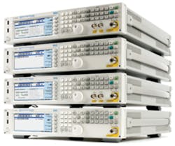
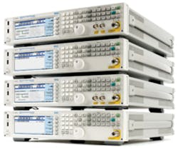
Figure 1. X-Series Signal Generators
Courtesy of Agilent Technologies
Riadh Said, signal generators platform manager at Agilent Technologies’ microwave and communications division, cited several applications that the company’s new X-Series Signal Generators (Figure 1) can address, including emerging IEEE 802.11ac1 wireless networking equipment.
“Because the 802.11ac WLAN combines bandwidths to 160 MHz with constellations as dense as 256 QAM, it places severe demands on a signal generator to deliver both modulation bandwidth and accuracy,” Said noted. “Using our N7617B Signal Studio for WLAN software, we now can create 160-MHz-wide 802.11ac signals in one instrument with EVM as low as 0.4% over the full 160-MHz bandwidth.” He said that this performance represents a substantial improvement over previous methods that would require external wideband IQ arbitrary waveform generators plus a vector signal generator for upconversion.
“Not only is this two-box setup complex and cumbersome,” Said explained, “but it also can introduce IQ amplitude and phase mismatch as well as time-skew errors. The result is poor EVM performance that the engineer must manually calibrate out of the system for every frequency and power level tested.” With the new MXG X-Series Signal Generator, he added, engineers can quickly load the 802.11ac signal to accelerate their development schedules.
Said cited additional applications areas: “The X-Series Signal Generators have a powerful internal real-time baseband generator and processor-accelerator ASIC.” The ASIC, he said, supports a large number of real-time applications in cellular communications, wireless networking, audio/video broadcasting, and navigation (including GPS and GLONASS systems).
He noted that the generators’ real-time generation capabilities support creation of complex signal scenarios of extremely long durations, citing satellite navigation as an example: “The MXG and EXG can generate signals representing up to 32 channels of GPS and GLONASS satellites with real-time control of satellite visibility and power with up to 24 hours of simulation time. Previously, engineers could only simulate GPS or GLONASS signals with dedicated test equipment. With the X-Series Signal Generators, they now have a general-purpose source that not only can support GPS and GLONASS, but also 2G, 3G, and 4G cellular standards and more.” Such capabilities, he added, are especially useful with devices such as smart phones where one handset may have a variety of radios plus a navigation receiver.
Said cited another advantage of real-time generation—the capability to do closed-loop testing, which is of increasing importance in addressing the latest digital wireless standards. “Closed-loop testing is especially valuable in throughput testing of real-world channels,” he said. “In testing such as LTE HARQ, the X-Series Signal Generators can receive TTL-level feedback signals and reconfigure the transmission signal on the fly while maintaining the link,” enabling more realistic testing of throughput over impaired channels. Previously, he explained, BTS development engineers had to purchase expensive dedicated LTE mobile device emulators to run HARQ tests.
Radar and Defense Test
With respect to defense applications, Leonard Dickstein, marketing manager at Giga-tronics, commented on how requirements are changing. He explained, “In the Cold War, we needed to detect high-velocity vehicles such as supersonic jet fighters. This drove how we optimized the performance of most radar and electronic warfare systems and their associated test equipment. While a requirement for this capability still exists, in short-term military-to-military engagements, most modern engagements—be it monitoring factions in the Middle East or analyzing unscrupulous activity occurring at countries’ borders—have to deal with much slower targets, such as vehicles, mules, and individuals.”
And, Dickstein explained, slow-moving targets pose significant challenges for Doppler radar systems: “For example, let’s go back to the good old days. If a hostile jet fighter is traveling head-on toward our radar at about 300 mph and we illuminated it using a pulse transmitted in the X-band—say, 10 GHz—we will see a difference in frequency from the original and the reflected of approximately 9 kHz. The amplitude of the reflection, of course, is very small compared to that of our original signal, and to be able to detect it requires that the phase noise or frequency stability of the system synthesizer or local oscillator (LO) is not dominant at this reflection frequency.”
Dickstein continued, “I picked this example specifically to outline that most microwave signal generators have some phase-noise optimization around the 10-kHz offset frequency range. In fact, most X-Band frequency synthesizers and microwave test equipment usually quote phase noise at a center frequency of 10 GHz with a 10-kHz offset.”
But, Dickstein added, “What if our hostile target is now a heavily laden donkey approaching our border on an overcast winter night or a convoy of vehicles in a desert sandstorm? At a maximum speed of about 10 mph, the Doppler frequency shift using the same X-band transmitter will be about 300 Hz. So, if you have been tasked with designing the next generation of surveillance radars or a moving target indicator system (MTI), close-to-carrier phase noise is a critically important factor. Doppler radar relies on detecting frequency changes.”
The emerging surveillance radar market, he said, requires separation of slow-moving targets from land clutter. “This means that the radar has to deal with smaller and smaller frequency changes. Modern microwave signal-generator design needs to take this evolving requirement into account and incorporate both a very stable frequency reference combined with the capability to synthesize signals at higher and higher frequencies, reducing the need for frequency doubling and keeping close-in phase noise to a minimum,” Dickstein concluded.
Anritsu also is adapting its signal generators for radar test. Walt Strickler, senior product manager at Anritsu, said, “RF/microwave communications systems are using higher order modulation schemes to increase bit rates and operate at higher bandwidths. This makes them more susceptible to errors if the phase noise of their local oscillators is too high. For example, a certain phase noise level may not affect a QPSK signal but will cause symbol errors on a 16 QAM signal.”
Anritsu touts its MG3690C Series Generators for radar applications. Said Strickler, “The low phase noise of the MG3690C means that DUTs are stimulated with known-good signals, enhancing the integrity of the measurement and reducing time spent locating test-equipment-induced measurement problems.”
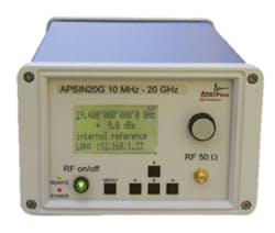
Figure 2. Low-Power APSIN20G Signal Generator
Courtesy of AnaPico
Jakub Kucera, product manager at AnaPico, also discussed radar and related applications. His company’s Model APSIN20G (Figure 2), he said, offers switching speeds and fast pulse modulation capabilities that enable it to serve in radar simulation applications. In addition, he noted that the unit’s low-power operation (less than 15 W) permits internal battery powered operation for field use in installation and maintenance as well as defense and aerospace applications, replacing heavy, YIG-based, relatively slow-switching instruments with high power dissipation.
The low-power capabilities also are welcome in crowded labs, Kucera said, making noisy cooling fans unnecessary. Indeed, he continued, the APSIN20G addresses applications requiring low-phase-noise CW or modulated signals—it can serve as an LO replacement, a general-purpose lab source, or a PA driver source, for instance. He noted that the APSIN20G uses a combination of fractional dividers and phase- and frequency-locked loops to provide its low phase noise at moderate power consumption without sacrificing switching speed. The unit can switch in 200 µs and offers frequency resolution below 1 mHz.
Component Manufacturing Test
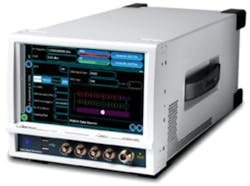
David Asquith and Neil Thomas, technical product manager and principle design engineer, respectively, at Aeroflex, cited component test as a target market. “One application for the S-Series SGA Analog Signal Generator (Figure 3) is the testing of analog-to-digital converters.” An ADC has two input ports, its analog signal input and its clock input, that are critically susceptible to jitter and other spurious artifacts. “Any jitter on the analog input translates to amplitude noise on the ADC’s output, affecting the ADC’s signal-to-noise ratio,” an adverse effect that becomes increasingly critical as the frequency range of ADCs increases.
Figure 3. S-Series SGA Analog Signal Generator
Courtesy of Aeroflex
They noted that the jitter produced by a signal generator can be calculated by integrating the phase noise over a given bandwidth. “Close-in to the carrier, although the jitter is considerable, being of low frequency it is of little significance for most high-speed ADCs,” they explained. “Further out from the carrier, however, because the integration over a particular decade covers a much wider bandwidth, the jitter calculation rises considerably, so far-out phase noise and wideband noise become the significant contributors as they fall within the operating range of the ADC.”
While maintaining a level of performance that provides sufficient margin to ensure reliable testing for the ADCs, signal generators targeting ADC manufacturing also must support high-speed test. “For high-volume ADC manufacturing, speed of test is paramount, and therefore the capability of the signal source to lock to its next amplitude and/or test frequency is critical in minimizing test time,” they explained. “With RF level and frequency settling times of typically 100 µs, the S-Series SGA maintains its low phase noise profile while being five to 10 times faster than previously possible.”
Signal Generator Architectures
Vendors are employing various approaches to designing signal generators that meet the needs of today’s test applications. Asquith and Thomas at Aeroflex commented, “The test requirements found in RFIC design and manufacture call for signal sources with both low phase noise and high-frequency switching speed, requirements that are invariably in conflict, resulting in performance being optimized for one requirement or the other.” Aeroflex’s latest synthesizer design used in its S-Series Signal Generators, they said, has been optimized for both areas, with a typical phase-noise at 1 GHz of -135 dBc/Hz at a 20-kHz offset complementing its less than 100-µs switching speeds.
To achieve a wide frequency range (up to 6 GHz) with fine frequency resolution, they explained, Aeroflex engineers chose a multiloop synthesizer design that uses two PLL loops: “One provides a low-noise RF signal capable of stepping across the required range in coarse steps while the second loop provides interpolation between the steps with a fine frequency resolution. Both loops are bought together to make the final output signal.”
For low-noise, high-frequency generation, Aeroflex employs a 135-MHz crystal and a fractional multiplier, a combination, they said, “…that provides a signal that covers 967 MHz to 1,350 MHz in steps of 22.5 MHz. Starting from a 135-MHz crystal results in a noise floor some 16 dB better than would be obtained by using a 22.5-MHz crystal.” In addition, an interpolation synthesizer provides a tuning range of 11.25 MHz to interpolate the 22.5-MHz steps of the high-frequency signal. Finally, the output loop adds the two low-noise signals together.
Achieving a fully settled frequency transition within 100 µs while maintaining low noise introduces a further set of challenges, Asquith and Thomas explained. Aeroflex engineers employed analog voltages in several places in the synthesizer to pre-tune VCOs and frequency-tune varactor bandpass filters. The tuning voltages have the conflicting requirements of being agile enough to move in microseconds yet quiet to subnanovolt levels and free of drift once settled. “We achieve this by using carefully selected low-noise DACs, switched-bandwidth passive filters, and filter capacitors with low dielectric absorption,” they noted.
In addition, Aeroflex used mixer-based phase detectors in PLLs in the fractional multiplier. These offer a very low noise floor but have a limited capture range. “Conventional methods of acquiring lock, such as search oscillators, would be far too slow for this application,” Asquith and Thomas said, noting that in the chosen approach, after a coarse pre-steer phase has steered the VCO frequency into the correct region, accurate tuning occurs before phase lock by means of a digital discriminator technique.
“An FPGA compares the frequency of the two signals at the phase detector and brings the VCO to the correct frequency by modifying the pre-steer voltage,” they explained. “Once the VCOs are close enough to lock, they lock and settle very quickly, due to minimum PLL bandwidths of 200 kHz, achieving frequency settling to 0.1 ppm in 100 µs. This represents an error band of only 100 Hz at a 1-GHz carrier frequency.”
Triple-Loop Design
Agilent’s new X-Series Signal Generators use several architectural enhancements to improve performance and functionality.2 According to Said, “For example, the new MXG X-Series Signal Generators implement a new triple-loop design and ‘frequency plan’ that result in substantial phase noise and spurious improvements both close to the carrier and at wide offsets.” The frequency plan, he said, is optimized for the triple-loop topology. “This triple-loop approach allows optimal frequency choices for effective filtering of undesirable signals that would otherwise become spurs, pushing them outside the bandwidth of the synthesizer circuits where modest filtering can heavily attenuate them.”
This approach also allows internal signal drive levels to be set higher, he said, reducing the relative level of broadband noise and improving dynamic range. As a result, the MXG delivers phase noise of -146 dBc at 1 GHz and 20 kHz offset and a spurious limit as low as -96 dBc at 1 GHz and >10-kHz offset.
Said explained, “Another key architectural enhancement is our baseband IQ accelerator ASIC,” which enables the EXG and MXG X-Series Signal Generators to provide modulation bandwidths to 120 MHz or 160 MHz, respectively. The modulation bandwidth features amplitude and phase response flatness as good as ±0.2 dB and ± 2°. Said noted that the X-Series achieves its bandwidth and accuracy using the proprietary ASIC and a factory-calibrated channel correction technique that extends from the baseband IQ modulator to the RF output.
Dickstein at Giga-tronics attributed the performance of the 2500B Series Microwave Signal Generators to the company’s knowledge of advanced YIG-tuned oscillator (YTO) design. The Giga-tronics design, he said, enables VCO tuning speed with the better spectral purity of a YTO. “The heart of the signal generator is the Accumulative High-Frequency Feedback (AHFF) Technology,” a patented technology developed by Giga-tronics engineers to overcome the limitations of fractional-N synthesizers.
“The AHFF Technology achieves low N numbers and fine resolution in a single loop by making use of a high-frequency reference source with a variable component to drive the PLL,” he said. “The PLL uses high-frequency, fractional-frequency pre-scaling to allow the ratio of the reference frequency to the output frequency to be quite low compared to traditional PLL synthesis methods” (Figure 4). He noted that the phase-frequency detector (PFD) and prescaling circuitry are Giga-tronics-proprietary low-noise designs, adding that careful power supply filtering and mechanical shielding also are essential.
Figure 4. 2500B Frequency Synthesis Phase-Lock-Loop, Pulse Modulator, and ALC Block Diagram
Courtesy Giga-tronics
In addition, he said, a fast “List Mode” engine steps frequency and amplitude from an embedded table, eliminating bus transfer delays. Further, the instrument’s ALC loop is optimized for fast amplitude switching speed.3
Anritsu has included noise mitigation techniques and minimized requirements for signal multiplication in the MG3690C, enhancing leading phase-noise performance over a wide set of frequencies and offsets, according to Strickler. He added, “The MG3690C architecture features a frequency reference, a PLL circuit consisting of an oscillator and frequency division circuitry, and a frequency multiplier. Phase noise is transferred from the reference through the division ratio (N) of the PLL and the multiplication factor (M) of the multipliers by a factor of 20 log (N + M).”
To minimize the need for multiplication, he said, “Anritsu utilizes a YIG-tuned oscillator with a tuning range of 2 to 20 GHz.” In addition, he said, with respect to PLL circuitry, “Crystal filters are included to remove unwanted products in the signal. A parallel divider network, rather than a single division, has been designed into the PLL circuitry to correlate the noise of the dividers, effectively reducing their noise contribution. A mixer also is integrated as the phase detector in the PLL circuitry to avoid the jitter added from digital phase/frequency detectors.”
With respect to radar, Strickler said, the MG3690C can generate narrow-pulse-width (10-ns) signals as independent singlet, doublet, triplet, and quadruplet pulses. This approach, he said, “enables the user to simulate multiple radar scenarios. The MG3690C also has the capability to adjust delays between pulse 2 and pulse 3, allowing it to simulate multiple doublet returns, which is vital with today’s radar signals.” He added that having a wide frequency range (0.1 Hz to 70 GHz) provides the ability to generate baseband, IF, RF, and microwave signals to test all the elements of a radar system from a single instrument.
Continuing Innovation
Vendors are continuing to develop new signal generators to keep up with evolving communications technology. For example, in May Anritsu introduced the MG3710A Series, a family of vector signal generators that supports test applications involving LTE, LTE Advanced, W-CDMA/HSPA, CDMA2000, GSM, and PDC as well as WLAN, Bluetooth, and ISDB-T (see p. 38).
In addition, vendors will continue to augment the capabilities of their existing instruments. For instance, Rohde & Schwarz recently added functionality to its R&S SMU200A Vector Signal Generator. Equipped with the R&S SMU-K77 option, the R&S SMU200A simulates dynamic-fading scenarios for testing military radio-communications equipment, making it possible to verify the performance of military radios and optimize their hardware to enable smooth operation under harsh receiving conditions such as dynamic fading and multipath signal propagation. Fading simulation enables precise and repeatable tests in the lab and eliminates the need for expensive field or flight tests.
Test vendors will continue to adapt as products under test evolve. As Kucera at AnaPico explained, microwave region frequency bands—with their wider available spectral bandwidths—will become increasingly desirable alternatives to crowded RF bands. “Wireless communications drive modulation to a next level,” he said. “Sophisticated digital modulation schemes will become predominant for higher data throughput.” And instrument makers will have to keep pace.
References
1. Nelson, R., “Modular Instruments Address 802.11ac,” EE-Evaluation Engineering, June 2012, p. 32.
2. Innovations in Agilent X-Series Signal Generators, Agilent Technologies, Backgrounder, May 1, 2012.
3. Ten Things About the Giga-tronics 2500B Series Microwave Signal Generators, Giga-tronics, Application Note, 2012.
For More Information
Aeroflex
Agilent Technologies
AnaPico AG
Anritsu
Giga-tronics
Rohde & Schwarz


